راهنمای کاربر PhotoRobot Cube V5 / V6 / Compact
این کتابچه راهنمای کاربر دستورالعمل های فنی در مورد نصب، اتصال و استفاده از PhotoRobot Cube V5 / V6 / Compact را ارائه می دهد. این شامل دستورالعمل هایی در مورد نحوه نصب ربات مکعب به عنوان نگهدارنده تنه مانکن چرخان است. هدف این کتابچه راهنما پشتیبانی از مشتریان PhotoRobot در طول مونتاژ دستگاه خود، اولین استفاده از آن و در اپراتورهای خط تولید است.
توجه داشته باشید: اولین نصب دستگاه PhotoRobot همیشه باید توسط یک مرجع مجاز PhotoRobot انجام شود. مقامات دارای مجوز نصب PhotoRobot یک توزیع کننده تایید شده یا نماینده خود سازنده هستند.
مهم: همیشه قبل از هر گونه نصب خود یا اولین استفاده، ابتدا به اطلاعات و دستورالعمل های ایمنی PhotoRobot علاوه بر دفترچه راهنمای ارائه شده به طور خاص با دستگاه خود مراجعه کنید.
مکعب V5 / V6 / جمع و جور اولین استفاده و نصب
با تشکر از شما و تبریک برای خرید مکعب PhotoRobot! دستگاه شما نشان دهنده چندین دهه تجربه حرفه ای، دانش فنی و نوآوری در عکاسی خودکار است. طراحی هر ربات با در نظر گرفتن شماست. در همین حال، این نرم افزار در حال توسعه مداوم است - متناسب با نیازهای منحصر به فرد و در عین حال با هر به روز رسانی از کل اکوسیستم PhotoRobot بهره مند می شود.
به PhotoRobot خوش آمدید. از این مستندات فنی در Cube V5 / V6 / Compact PhotoRobots برای آشنایی با این فناوری و دستورالعمل های مربوط به مونتاژ و اولین استفاده از راه حل استفاده کنید.
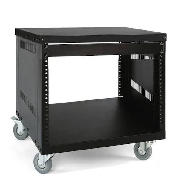
1. توضیحات محصول - مکعب V5 / V6 / جمع و جور
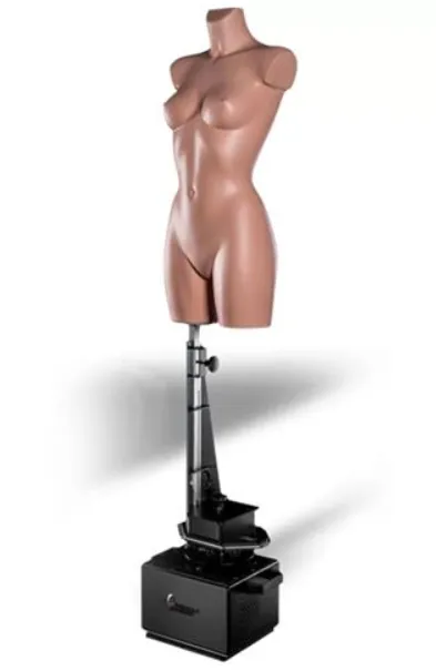
دستگاه های PhotoRobot Cube V5 / V6 / Compact یکی از همه کاره ترین ربات های استودیوی عکس هستند. هر مکعب قادر به عملکرد مستقل یا در ترکیب با سایر PhotoRobot ها است و دارای تنظیمات برای 3 حالت مختلف کار است. مکعب به عنوان یک سکوی عکاسی چرخان، در حالت تعلیق شیء و به عنوان یک نگهدارنده نیم تنه مانکن چرخان عمل می کند.
ویژگی های کلیدی مکعب PhotoRobot عبارتند از:
- استفاده مستقل یا در حال استفاده در ترکیب با PhotoRobot های سازگار
- راه اندازی سریع به عنوان یک صفحه گردان 360 یا در حالت تعلیق شی
- پشتیبانی از نگهدارنده تنه مانکن یا سکوی چرخان
- سازگار با مانکن های عکاسی در انواع و اندازه های مختلف
- در نسخه های Cube V5، V6 و Compact برای تطبیق پذیری بیشتر موجود است
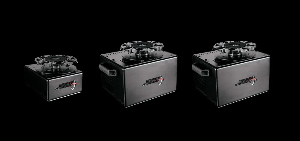
1.1. نمای کلی دستگاه - Cube V5 / V6 / Compact
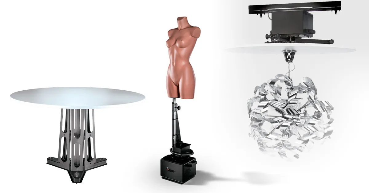
PhotoRobot's Cube V5، Cube V6 و Cube Compact در سه پیکربندی مختلف کار می کنند. تنظیمات استاندارد شامل استفاده از دستگاه به عنوان یک پلت فرم عکاسی چرخان یا معلق کردن اشیاء در هوا برای عکس گرفتن است. از طرف دیگر، می توان دستگاه را به عنوان یک پایه چرخان برای نصب تنه مانکن تنظیم کرد.
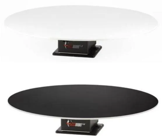
الف) راه اندازی پلت فرم عکس / روتاری 360:
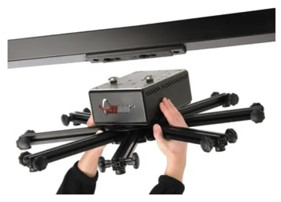
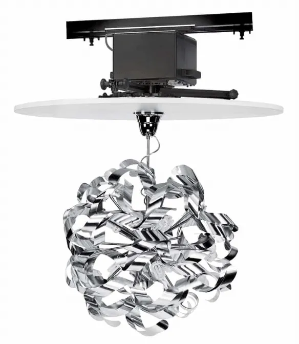
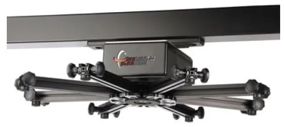
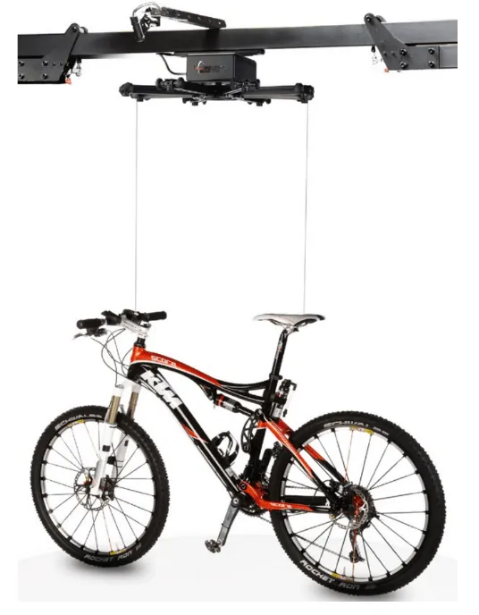
ب) حالت تعلیق 360 / روتاری:
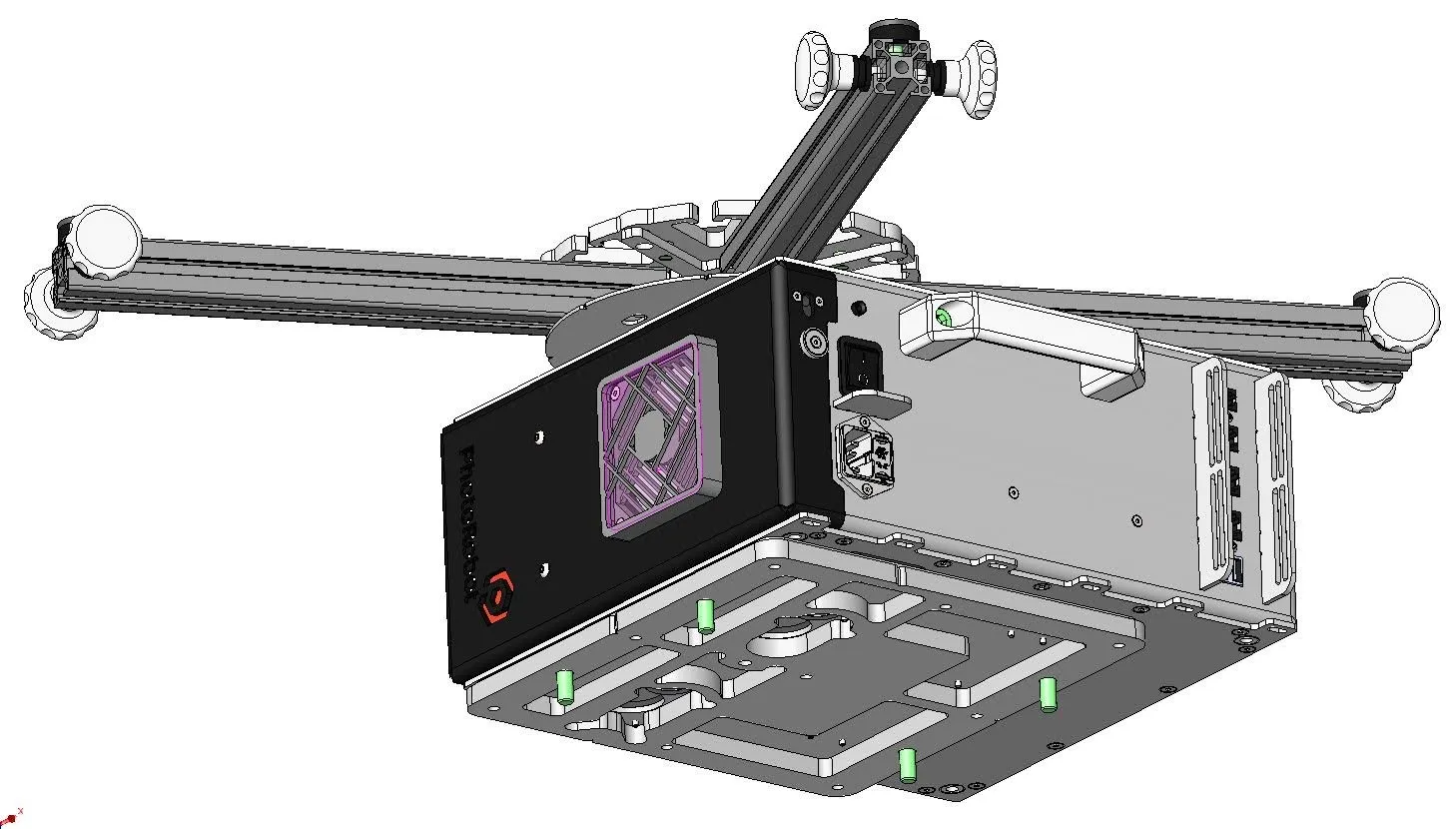
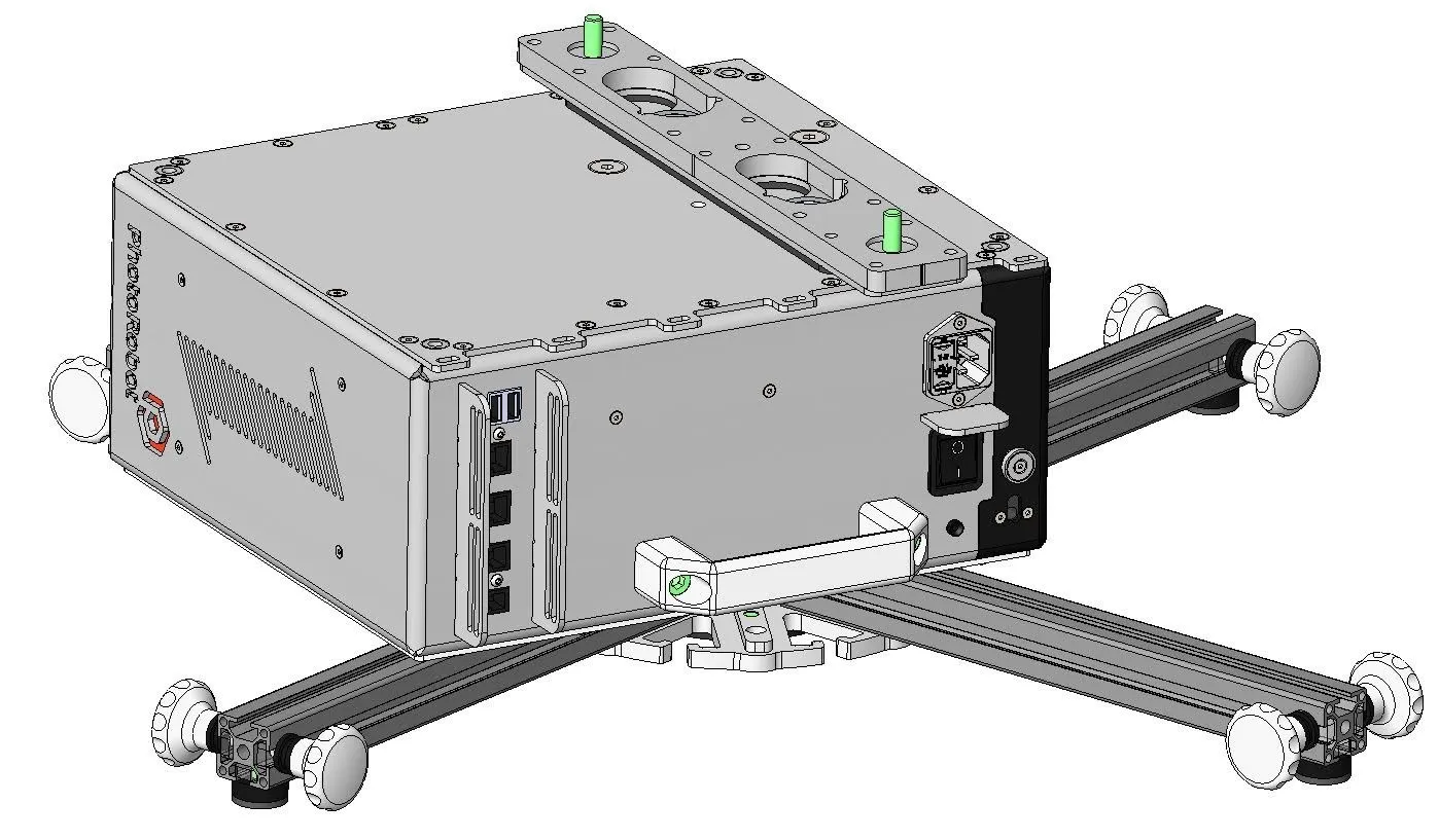
ج) نگهدارنده نیم تنه مانکن چرخان:
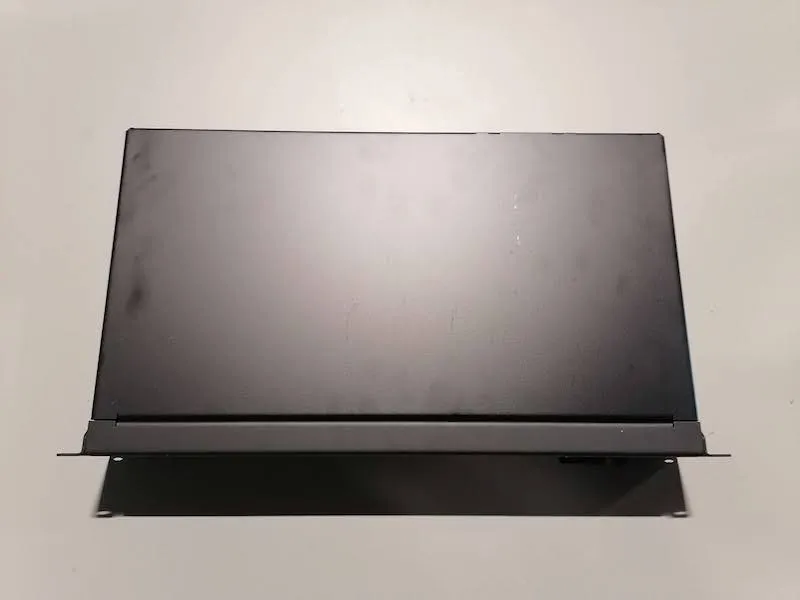
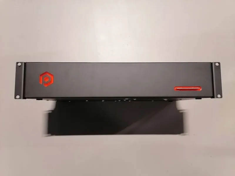
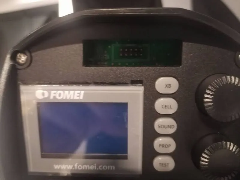
توجه داشته باشید: واحد کنترل مکعب V5 و مکعب V6 یک جزء جداگانه اما جدایی ناپذیر برای دستگاه ها هستند. Cube Compact دارای یک واحد کنترل یکپارچه در داخل دستگاه است.
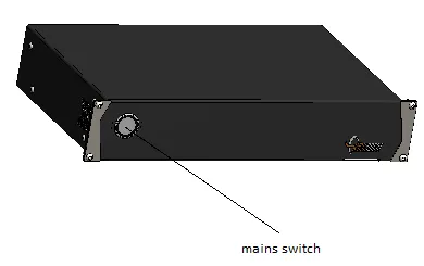
- تصویر بالا واحد کنترل مکعب V5 / Cube V6 را نشان می دهد.
1.2 پارامترهای فنی جمع و جور مکعب
پارامترهای فنی زیر برای Cube Compact وجود دارد.
- وزن: 26.21 کیلوگرم
- ابعاد: 337.5 x 373.5 x 209.5 میلی متر
- منبع تغذیه: 100 - 230 ولت ، 50 هرتز ، فیوز T1.6 A (230 ولت) ، T3.15 A (115 ولت)
- ظرفیت بار: 130 کیلوگرم برای نصب پایین و بالا
- گشتاور شفت خروجی: 143.5 نیوتن متر
- سرعت: 0 -17 1.min-1
1.3 لوازم جانبی جمع و جور مکعب
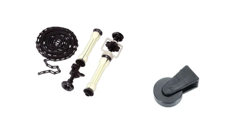
Cube Compact دارای قطعات و لوازم جانبی زیر است.
الف) آویز:
ب) پایه پایین:
ج) پایه بالا:
د) پایه ماشین:
ه) صفحه:
و) پورتال:
1.4. بررسی اجمالی نصب و استفاده از Cube Compact
علاوه بر لوازم جانبی Cube Compact ، تنظیمات متعددی برای نصب و استفاده از Cube Compact وجود دارد. اینها شامل قطعات پیکربندی و تنظیمات زیر است.
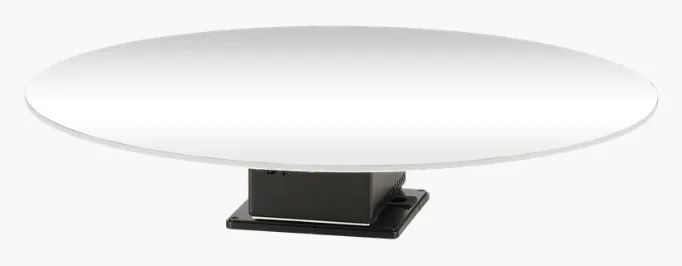
الف) صفحه بست پایین (برای بستن صفحه گردان دستگاه یا سیستم نصب):
ب) پلت فرم چرخشی مستقل محکم شده (برای ثبات بیشتر به کف بسته می شود):
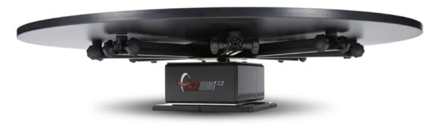
توجه داشته باشید: در این پیکربندی ، یک صفحه 95 سانتی متری با پایه نصب شده بر روی سطح کف پایدار وجود دارد. این دستگاه را در هنگام استفاده تثبیت می کند و برای جلوگیری از واژگونی عمل می کند. موارد استفاده از آن شامل ارائه اجسام کوچک و متوسط ، حداکثر اندازه 60 - 65 سانتی متر است.
ج) پلت فرم چرخشی ایستاده (با پایه دستگاه در حال استفاده):
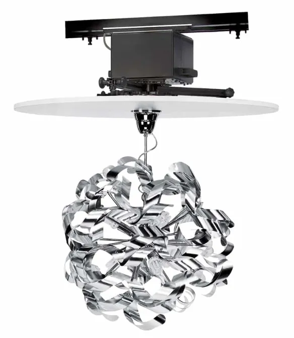
د) حالت تعلیق چرخشی 360 (نصب وارونه به پورتال بالا):
1.5 توقف اضطراری جمع و جور مکعب
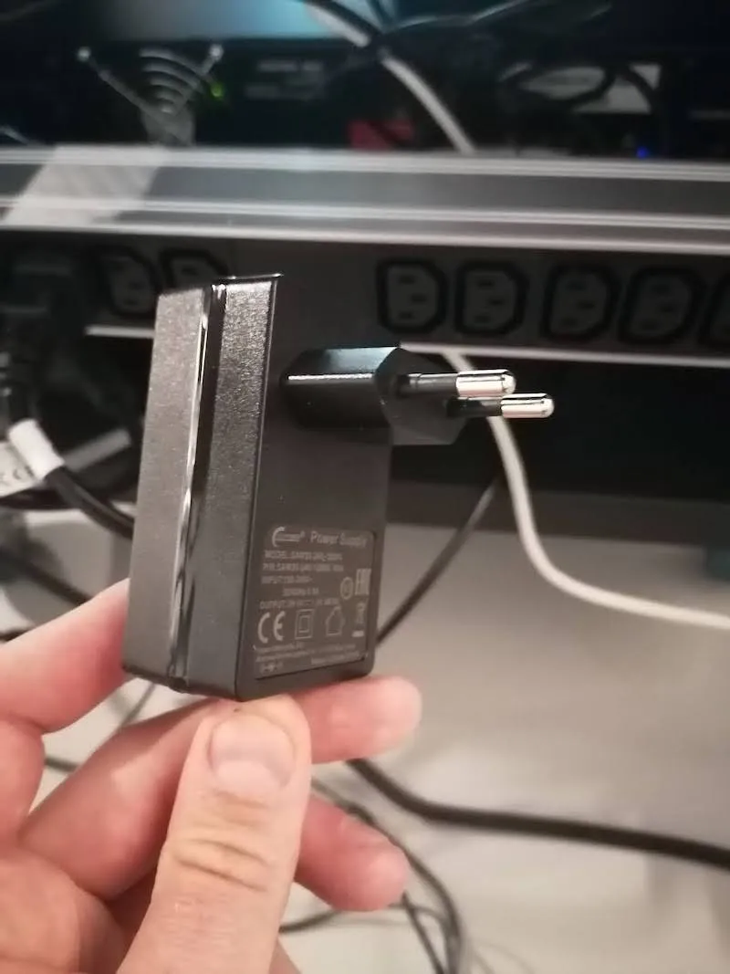
برای انجام توقف اضطراری، با کشیدن سیم برق از پریز ، دستگاه را از شبکه برق جدا کنید.
1.6 مکعب V5 / V6 / تعمیر و نگهداری جمع و جور
توجه داشته باشید که لازم است دستگاه را تمیز و در محیطی خشک و کنترل آب و هوا با دمای ثابت نگه دارید. گرد و غبار را فقط با آگهی پاک کنیدamp پارچه و از مواد شیمیایی یا حلال برای تمیز کردن استفاده نکنید.
با طراحی، تجهیزات باید طبق قوانین محلی تحت بازرسی ها و بازنگری های منظم قرار گیرند. پس از پایان چرخه عمر آن، تجهیزات الکتریکی باید با تحویل به سیستم جمع آوری زباله های الکترونیکی دیکته شده توسط قوانین محلی، به درستی دفع شوند.
2. اولین استفاده - PhotoRobot Cube V5 / V6 / Compact
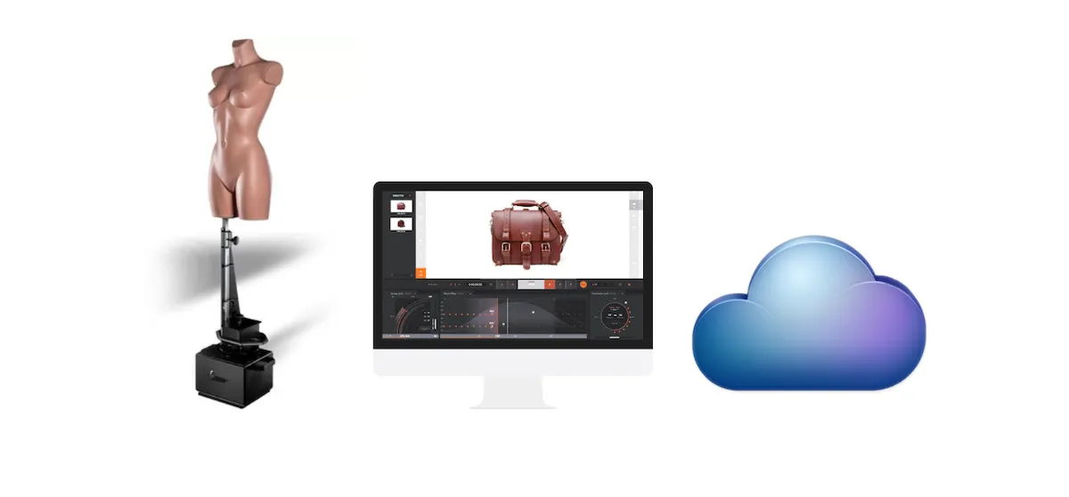
قبل از اولین استفاده از PhotoRobot، درک مفهوم پشت این فناوری ضروری است. PhotoRobot یک راه حل همه کاره انقلابی برای اتوماسیون عکاسی محصول و اشیاء است. از منظر فنی، این یک واحد ماژولار متشکل از سخت افزار و نرم افزار است. بنابراین، لازم است که خود PhotoRobot از طریق همان شبکه رایانه ای که آن را اداره می کند متصل شود. شبکه همچنین برای دسترسی به خدمات PhotoRobot که در فضای ابری اجرا می شوند، باید به اینترنت متصل باشد. سپس شرایط زیر وجود دارد که همیشه باید رعایت شود.
- باید یک واحد کنترل PhotoRobot متصل به شبکه محلی وجود داشته باشد.
- یک کامپیوتر برای اجرای رابط کاربری گرافیکی سرویس یا نرم افزار اپراتور به نام _Controls ضروری است.
- کامپیوتر باید به همان شبکه واحد کنترل PhotoRobot متصل باشد.
- شبکه باید به اینترنت متصل باشد.
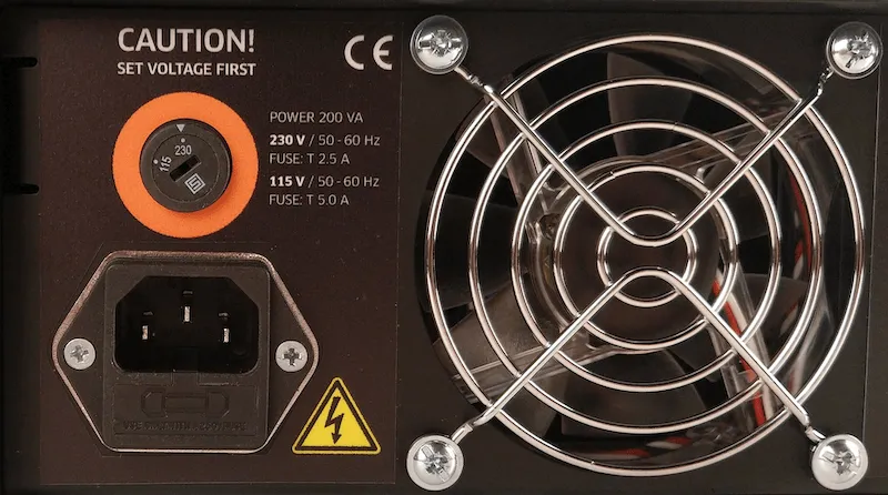
پس از اطمینان از اتصال PhotoRobot به رایانه و شبکه محلی، پارامترهای سیستم توزیع برق (به عنوان مثال ولتاژ و فرکانس) را بررسی کنید.
سپس، تنظیم برق واحد کنترل را بررسی کنید. باید با تمام پارامترهای سیستم توزیع برق مطابقت داشته باشد. اگر تنظیمات واحد کنترل مطابقت نداشت، به بخش بعدی در مورد تنظیم برق واحد کنترل مراجعه کنید.
در صورت انطباق ، با اتصال واحد کنترل به شبکه از طریق کابل اترنت ادامه دهید.
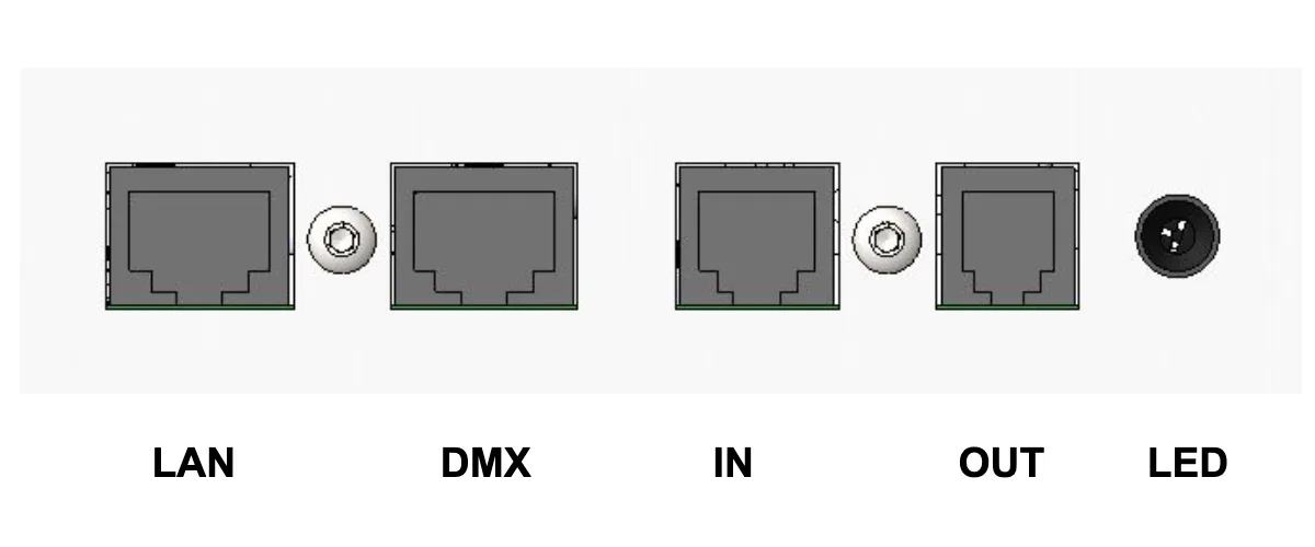
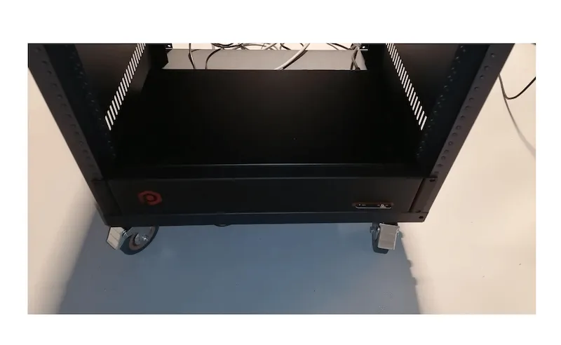
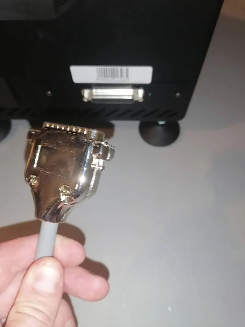
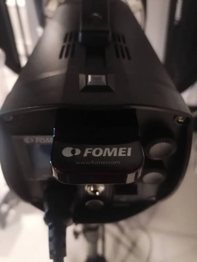
توجه داشته باشید: برای مدل های Cube V5 / V6 ، واحد کنترل یک دستگاه جداگانه است. کانکتور RJ45 را در پشت واحد کنترل پیدا کنید. Cube Compact دارای واحد کنترل یکپارچه در دستگاه است. کانکتور RJ45 را در پشت ربات مکعب پیدا کنید.
2.1. راه اندازی قدرت واحد کنترل
برای بررسی تنظیمات برق واحد کنترل، مدل قدیمی تر واحد کنترل دارای یک جلدtage انتخابگر دستی در پشت دستگاه است.
از طرف دیگر، واحد کنترل مدل جدیدتر انتخابگر ولتاژ ندارد و دارای محدوده عملکردی در 110 ولت - 240 ولت است.
اگر در مورد تنظیم برق واحد کنترل مطمئن نیستید، برای کمک از یک تکنسین متخصص PhotoRobot با پشتیبانی فنی PhotoRobot تماس بگیرید.
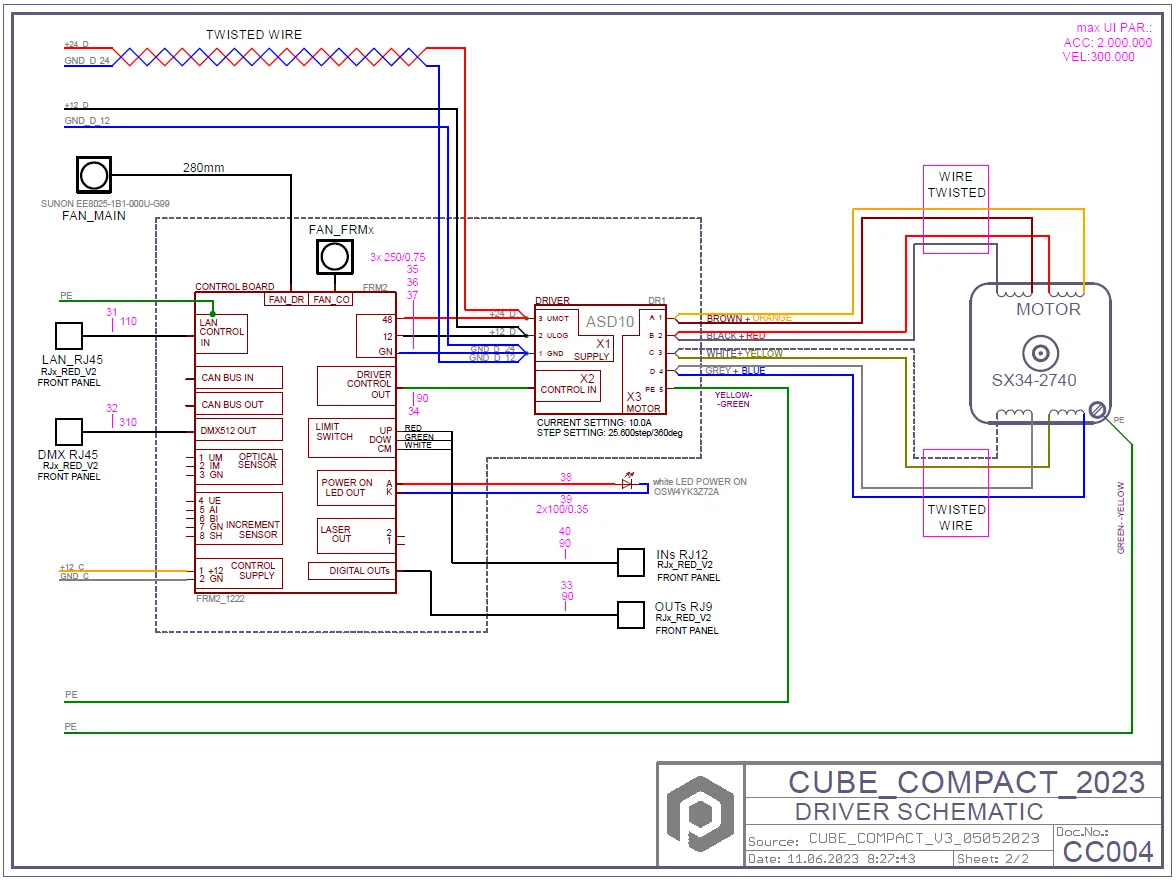
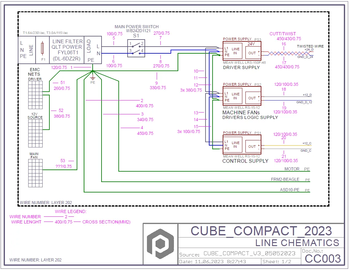
2.2 نمودار الکتریکی فشرده مکعب
2.3. پیکربندی شبکه
برای پیکربندی شبکه برای برقراری ارتباط صحیح با PhotoRobot، شرایط زیر باید در شبکه رعایت شود.
- سرور DHCP در شبکه اجباری است.
- ارتباط پورت های TCP 7777، 7778 باید مجاز باشد.
- پخش UDP در پورت 6666 باید مجاز باشد
- اتصال به اینترنت اجباری است.
- *. دسترسی photorobot.com باید مجاز باشد.
- دسترسی as-unirobot.azurewebsites.net باید مجاز باشد.
- اتصال سیمی PhotoRobot به LAN توصیه می شود.
- در صورت لزوم برای اطلاعات بیشتر به پیش نیازهای شبکه PhotoRobot Detailed مراجعه کنید.
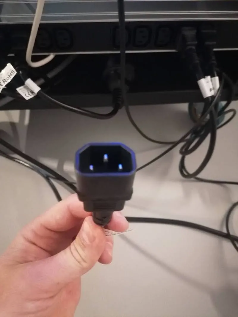
- دوشاخه برق را به پریز برق وصل کنید.
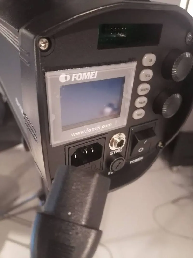
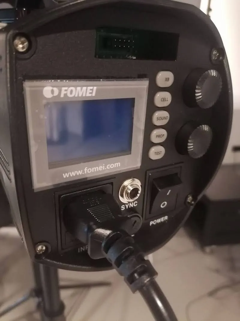
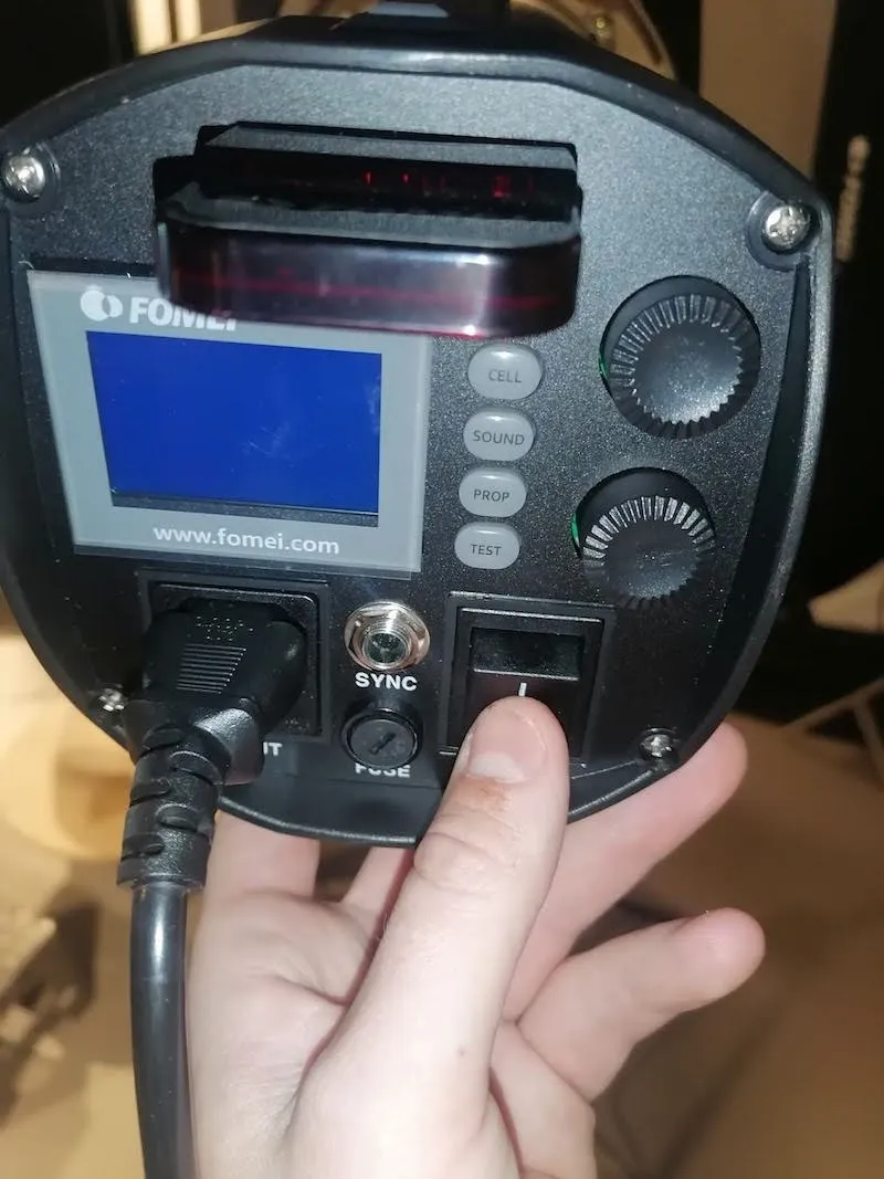
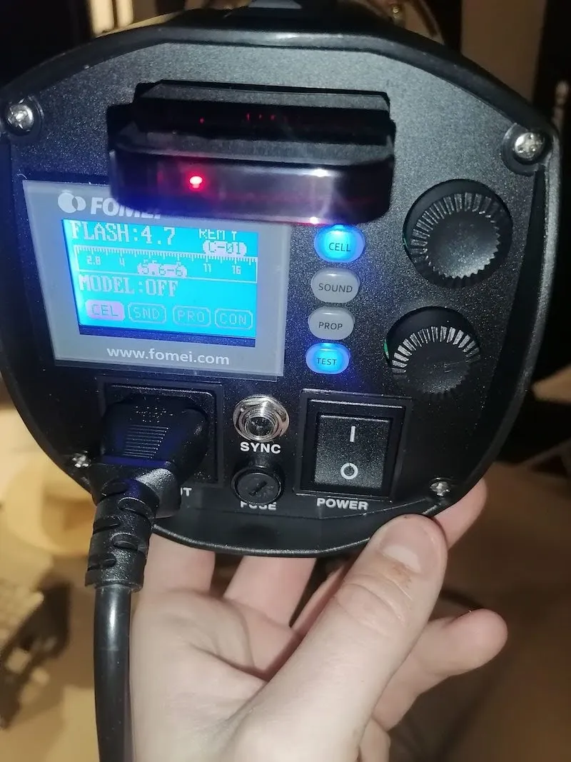
در مرحله بعد، کلید برق را روی واحد کنترل مکعب V5 / V6 (یا در پشت Cube Compact) فشار دهید. چراغ وضعیت زمانی که برای کار آماده شود، از چشمک زدن به نور پیوسته به سیگنال تغییر می کند.
2.4. آدرس IP PhotoRobot را در LAN پیدا کنید
پس از پیکربندی صحیح شبکه، لازم است آدرس IP PhotoRobot را در LAN جستجو و شناسایی کنید. برای این کار، برنامه PhotoRobot Locator مستقیماً در CAPP ادغام شده است برای جستجو و شناسایی آسانتر واحدهای کنترل در شبکه. اطمینان حاصل کنید که از بهروزترین نسخه CAPP برای دسترسی به این ویژگی استفاده میکنید.
سپس، برای شناسایی یک ربات در شبکه مستقیماً در CAPP، نسخه محلی CAPP را باز کنید، به تنظیمات بروید و روی رباتها / واحدهای کنترل کلیک کنید.
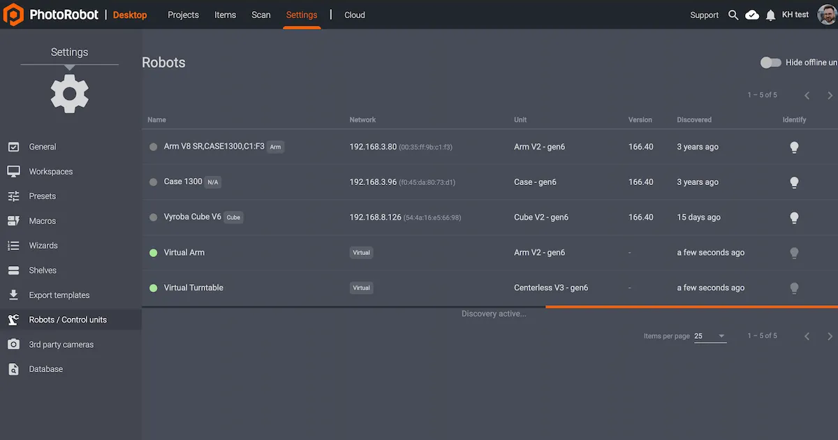
منوی رباتها / واحدهای کنترل ستونهایی با نام، شبکه، واحد، نسخه، کشف شده، و شناسایی برای هر ربات نمایش میدهد. اگر نقطه سمت چپ نام ربات سبز باشد، آنلاین است. کلیک کردن روی فیلد ربات، رابط وبسایت ربات را باز میکند. این کار همچنین باعث میشود چراغ LED روی واحد کنترل ربات سبز چشمک بزند تا شناسایی آن آسانتر شود.
اگر دانلود خارجی برنامه توسط مشتری مورد نیاز باشد، PhotoRobot Locator نیز برای دانلود iOS در دسترس است در دانلودهای حساب PhotoRobot.
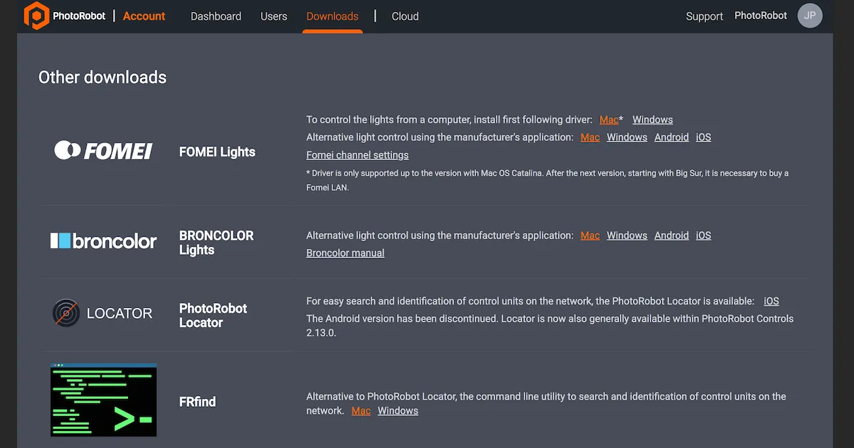
توجه: نسخه اندروید PhotoRobot Locator متوقف شده است.
بهعنوان جایگزین، ابزار خط فرمان FRFind برای MacOS یا Windows وجود دارد تا شبکه را جستجو کرده و واحدهای کنترل PhotoRobot را شناسایی کند. لینکهای دانلود FRfind را نیز در صفحه دانلودهای حساب PhotoRobot پیدا کنید.
2.5 تست اولیه - Cube V5 / V6 / Compact
برای آزمایش Cube V5 / V6 / Compact، سپس یک مرورگر وب را باز کنید و آدرس IP مرتبط با PhotoRobot خود را با فرمت URL وارد کنید. به عنوان مثال، وارد کنید: https://11.22.33.44 (اگرچه توجه داشته باشید که این آدرس فقط یک نمونه است). در صورت موفقیت، یک رابط کاربری اولیه راه اندازی می شود.
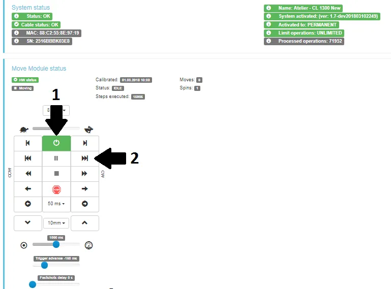
- موتورها را روشن کنید (فلش 1 بالا) و سعی کنید هر قسمت متحرک ربات را کار کنید (فلش 2 بالا). اگر ربات بر اساس دستورالعمل شما حرکت می کند، شما آماده هستید تا به طور منظم از دستگاه PhotoRobot خود استفاده کنید.
3. مونتاژ مکعب V5 / V6 و نگهدارنده نیم تنه مانکن
هنگام مونتاژ مدل های Cube V5 یا Cube V6، توجه داشته باشید که مونتاژ واحد کنترل و قفسه جداگانه ضروری است. این مورد در مورد Cube Compact صدق نمی کند. در صورت استفاده از Cube Compact، به بخش مونتاژ پس زمینه کاغذ بروید.
3.1 مونتاژ رک HD و واحد کنترل (V5 / V6)
3.1.1. برای مونتاژ واحد کنترل جداگانه Cube V5 و Cube V6، با مونتاژ قفسه شروع کنید. برای این کار، دستورالعمل های موجود در دفترچه راهنمای متصل به جعبه قفسه هنگام تحویل را دنبال کنید.
3.1.2. در مرحله بعد، واحد کنترل را از جعبه حمل و نقل کارتن آن پیدا کرده و باز کنید.
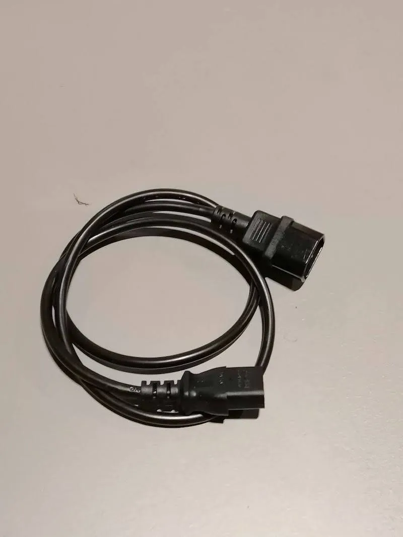
3.1.3. سپس، کابل های زیر را آماده کنید: کابل برق (طول 1 متر)، کابل کرکره، کابل موتور و کابل اترنت (طول 2 متر).
الف) کابل برق (طول 1 متر):
ب) کابل شاتر (طول 1 متر):
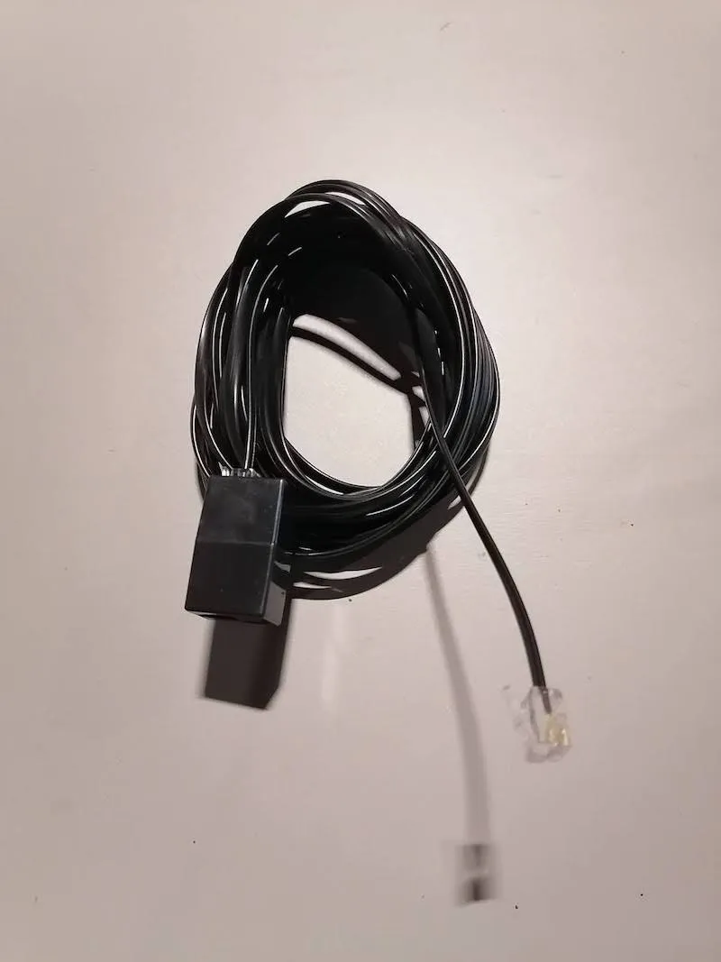
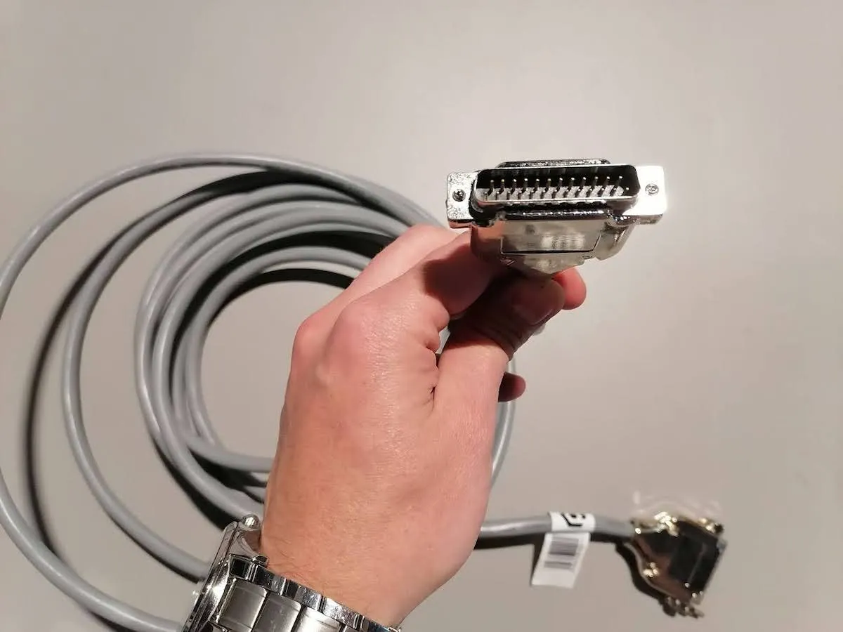
ج) کابل موتور:
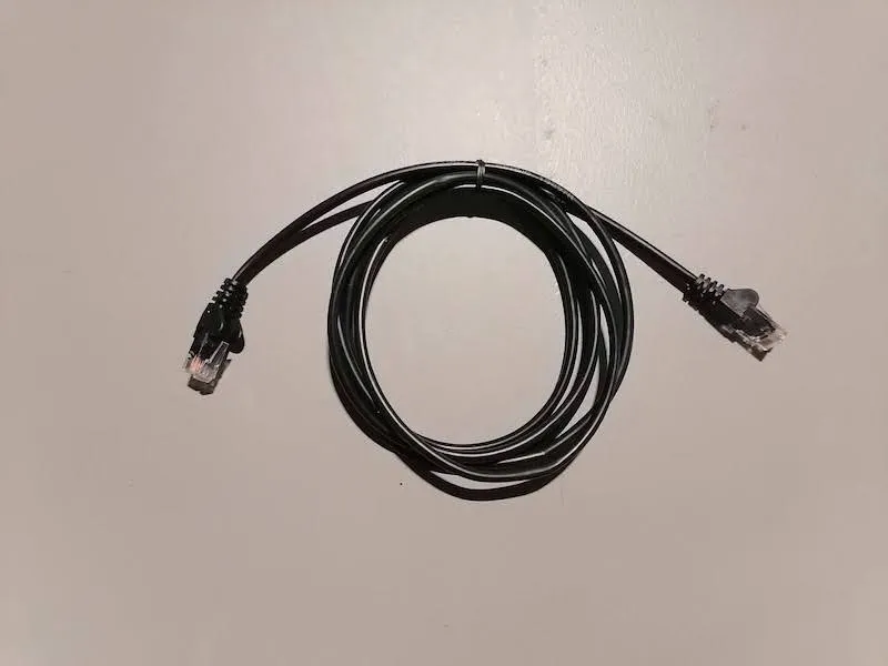
د) کابل اترنت (طول 2 متر):
3.1.4. هر کابل آماده شده در مرحله قبل را در قفسه قرار دهید.
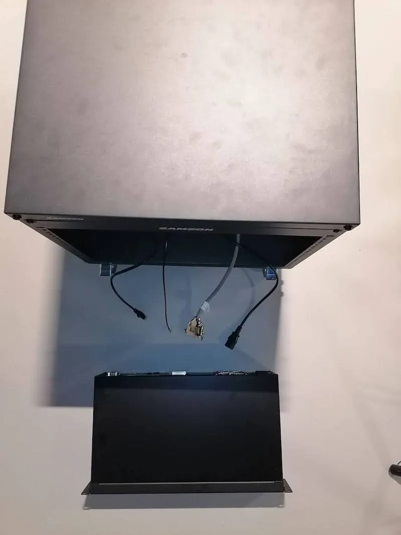
3.1.5. کابل های مراحل قبلی را به واحد کنترل وصل کنید.
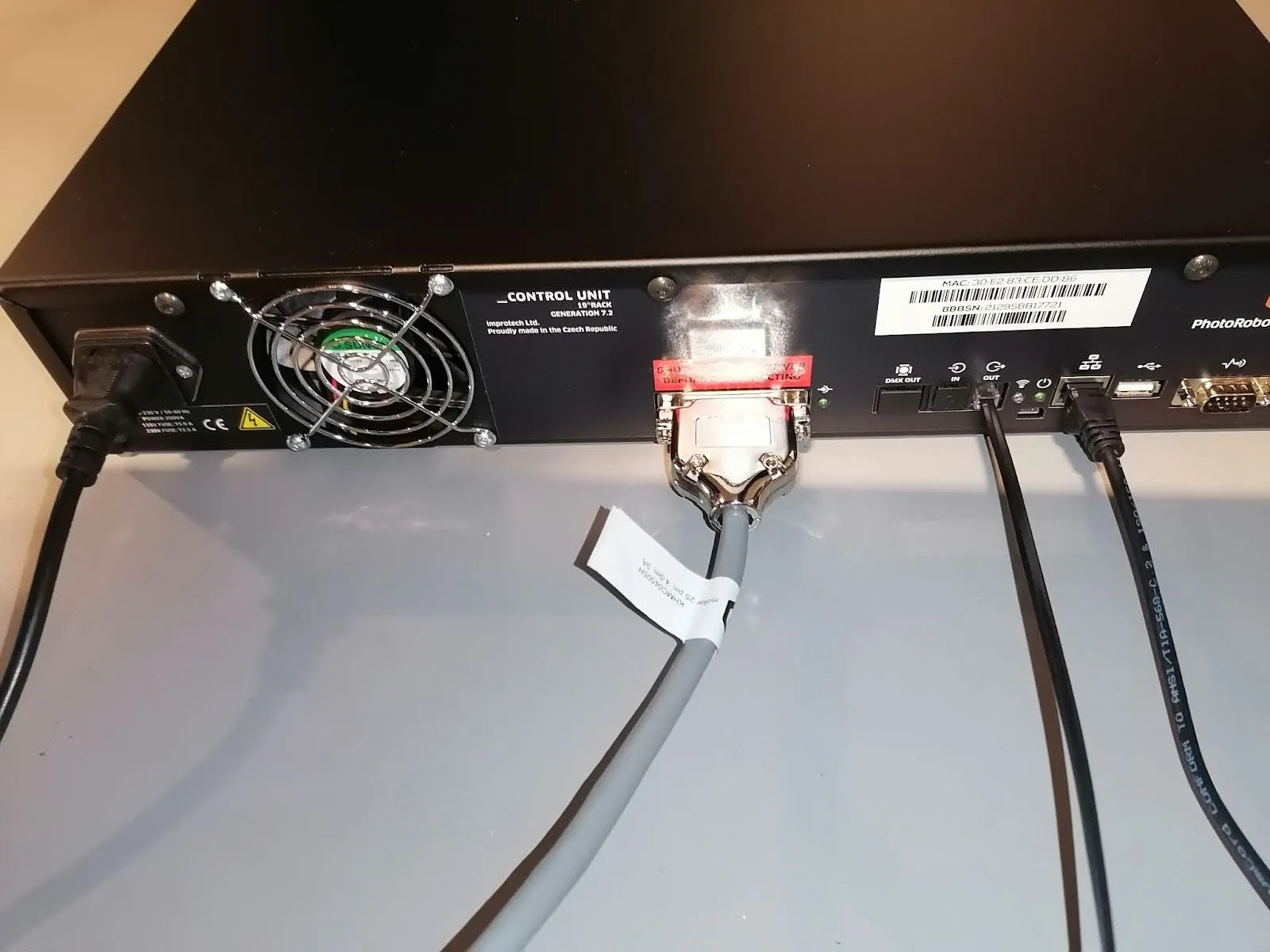
مهم: کابل موتور باید با استفاده از دو پیچ روی کانکتور محکم بسته شود. کابل شاتر به پورت OUT واحد کنترل متصل می شود.
3.1.6. واحد کنترل را در جعبه قفسه قرار دهید و پیچ ها را ببندید تا بسته شود.
3.2. مونتاژ لوازم جانبی و اتصالات
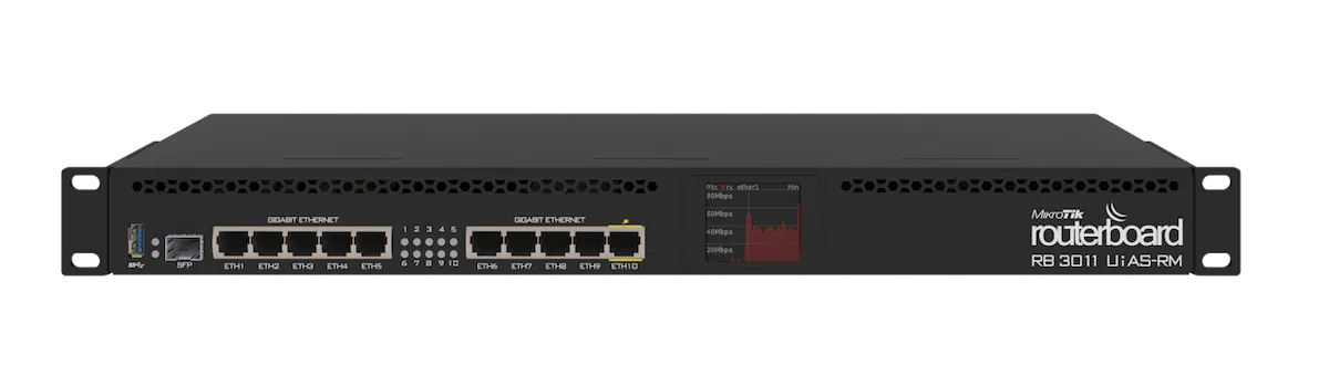
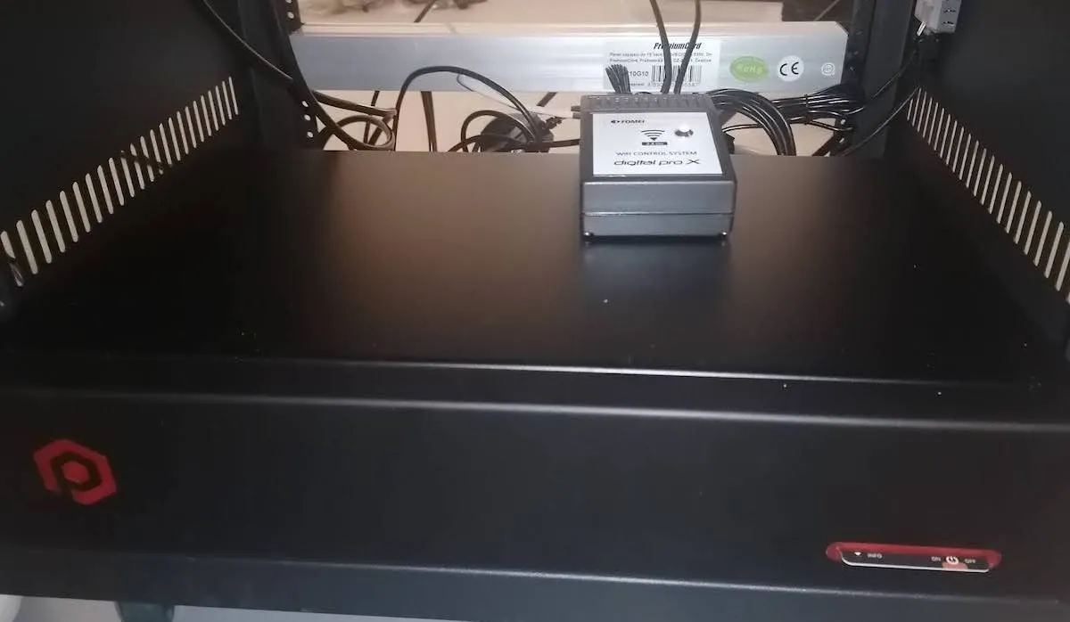
3.2.1. برای اتصال تمام لوازم جانبی Cube V5 / Cube V6، با باز کردن بسته بندی روتر از جعبه کارتن و سپس نصب نگهدارنده های قفسه شروع کنید. در مرحله بعد، کابل های برق یا آداپتور (بسته به نوع روتر) را وصل کنید و قبل از بستن روتر، روتر را در جعبه رک قرار دهید.
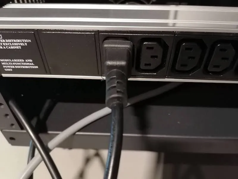
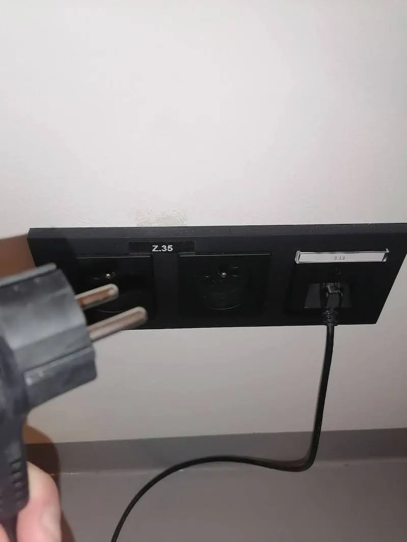
3.2.2. چند سوکت برق را با بستن آن با پیچ روی قسمت پایین پشت قفسه محکم کنید.
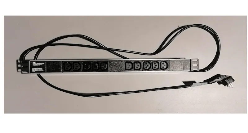
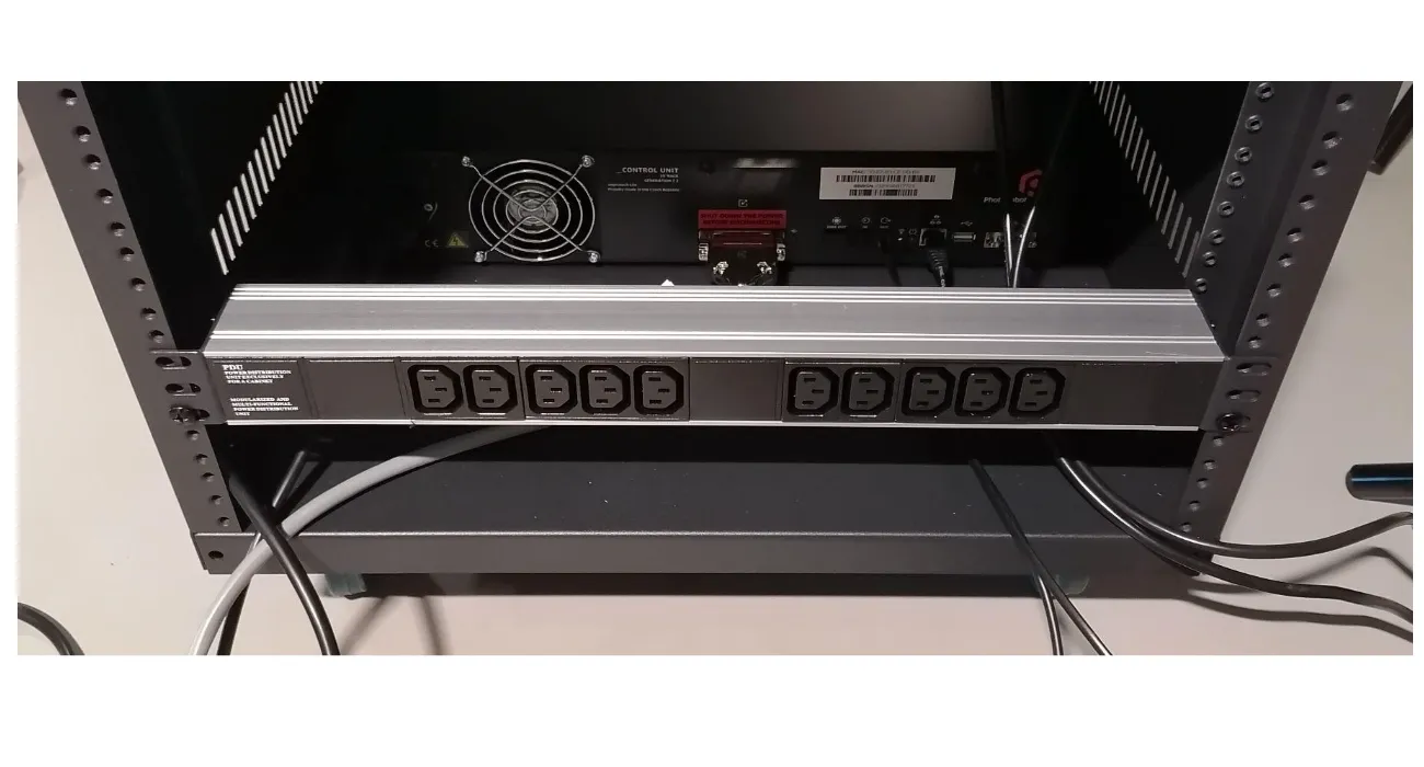
3.2.3. اگر روتر تحویل داده شده دارای آداپتور برق است، رابط آداپتور برق را پیدا کنید و آن را به هر کانکتور چند سوکت برق وصل کنید.
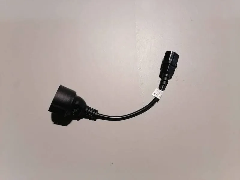
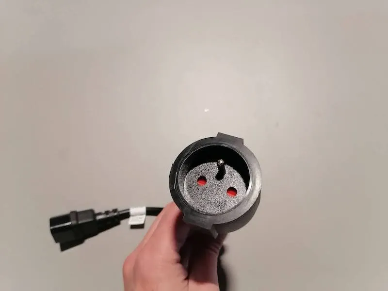
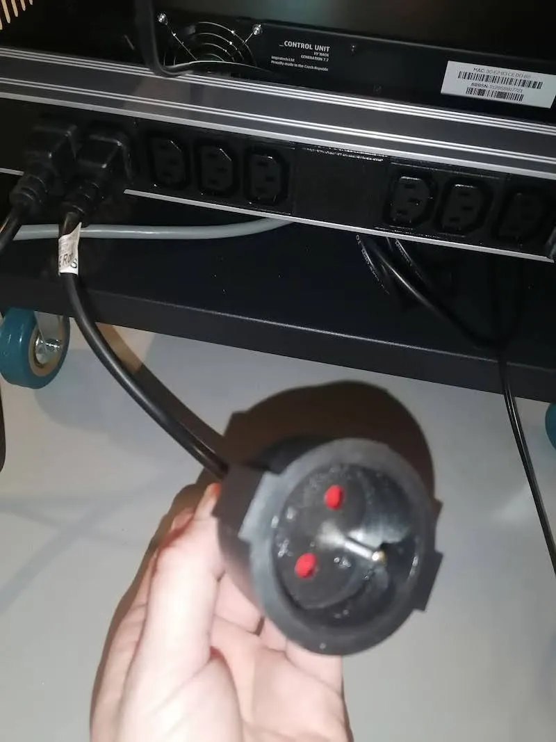
3.2.4. انتهای آزاد کابل برق واحد کنترل را پیدا کنید و آن را به چند سوکت برق وصل کنید.
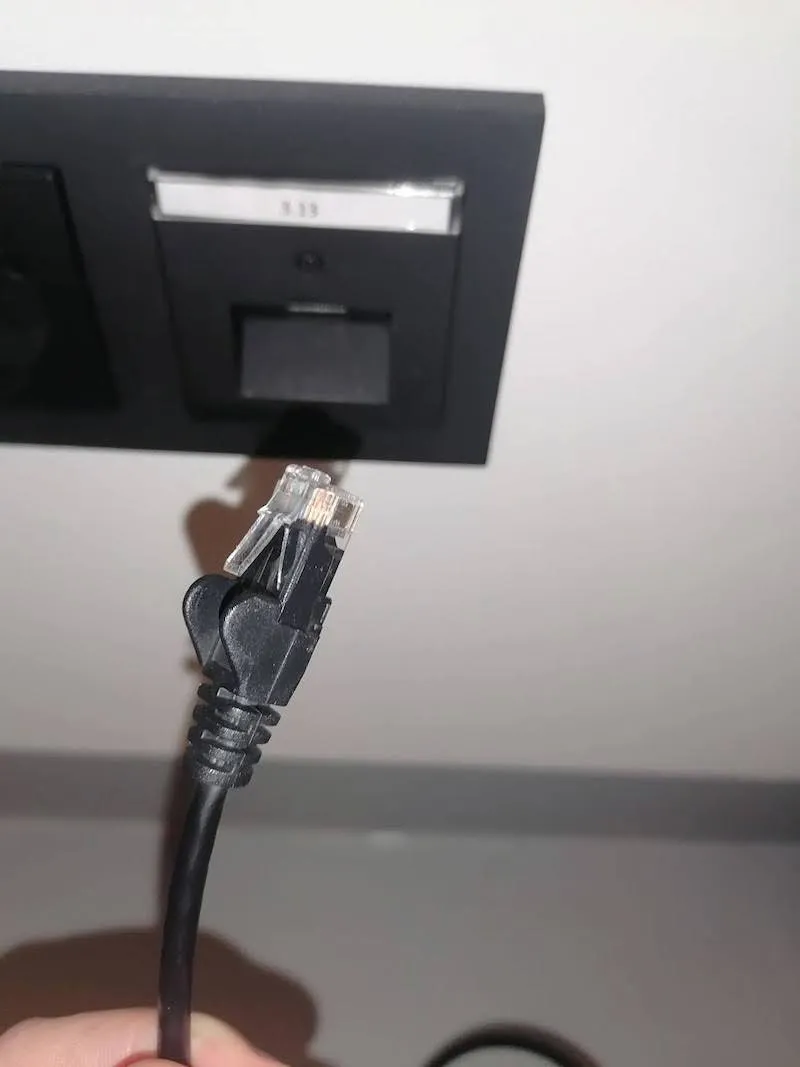
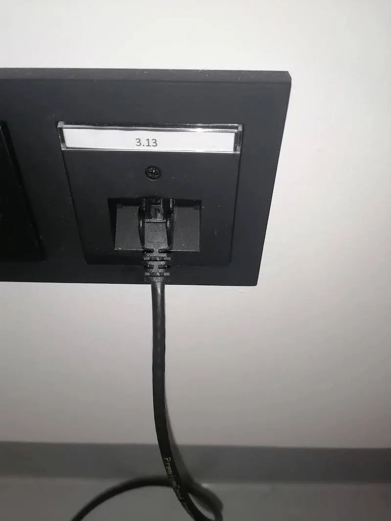
3.2.5. با استفاده از طولانی ترین کابل اترنت، کابل را به سوکت دیواری داده استودیوی خود وصل کنید. لطفا توجه داشته باشید که به طور پیش فرض انتظار می رود دسترسی به اینترنت از طریق این سوکت دیواری داده در دسترس باشد و بنابراین آدرس IP به طور خودکار به دست می آید.
3.2.6. سر دیگر کابل اترنت را به آخرین پورت روتر وصل کنید. بسته به نوع روتر، از پورت شماره 10 یا شماره پورت 13 استفاده کنید.
3.2.7. در مرحله بعد، انتهای آزاد کابل اترنت را از واحد کنترل با استفاده از هر پورت شماره 1-9 به روتر وصل کنید.
3.2.8. رابط آداپتور برق را پیدا کنید و آن را به چند سوکت برق وصل کنید.
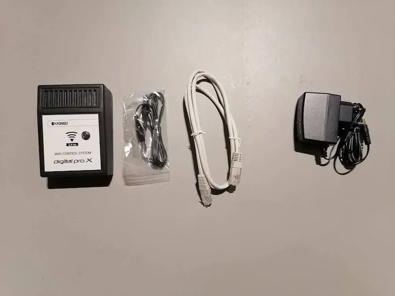
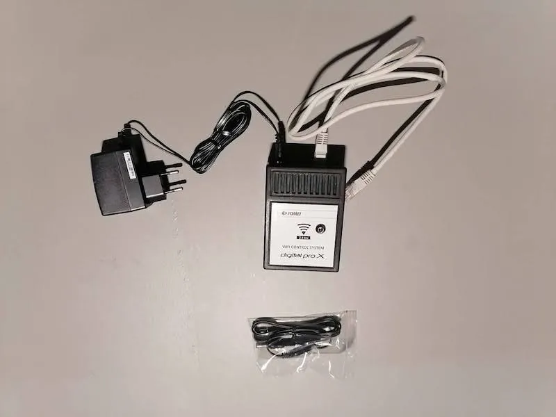
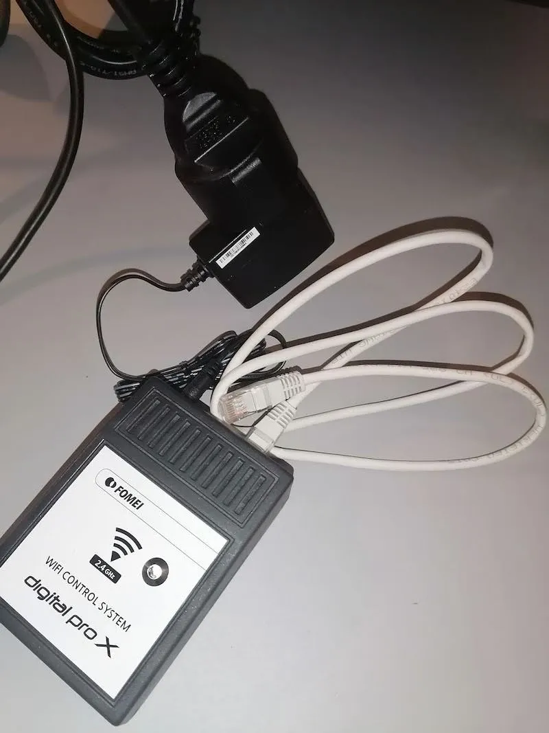
3.2.9. ماژول Wi-Fi را از جعبه کارتن خارج کنید و کابل اترنت 2 متری دیگری برای اتصال به ماژول Wi-Fi پیدا کنید. سر دیگر کابل اترنت با استفاده از هر پورت شماره 1-9 به روتر متصل می شود.
3.2.10. در مرحله بعد، در صورت استفاده از فلاش های Fomei، مبدل Wi-Fi و آداپتور برق Fomei را باز کرده و دستگاه ها را وصل کنید. در صورت استفاده از چراغ های Broncolor، به PhotoRobot - Broncolor Lights Management مراجعه کنید.
3.2.11. رابط آداپتور برق را به چند سوکت برق وصل کنید و سپس آداپتور را وصل کنید. انتهای دیگر کابل با استفاده از هر پورت شماره 1-9 به روتر متصل می شود.
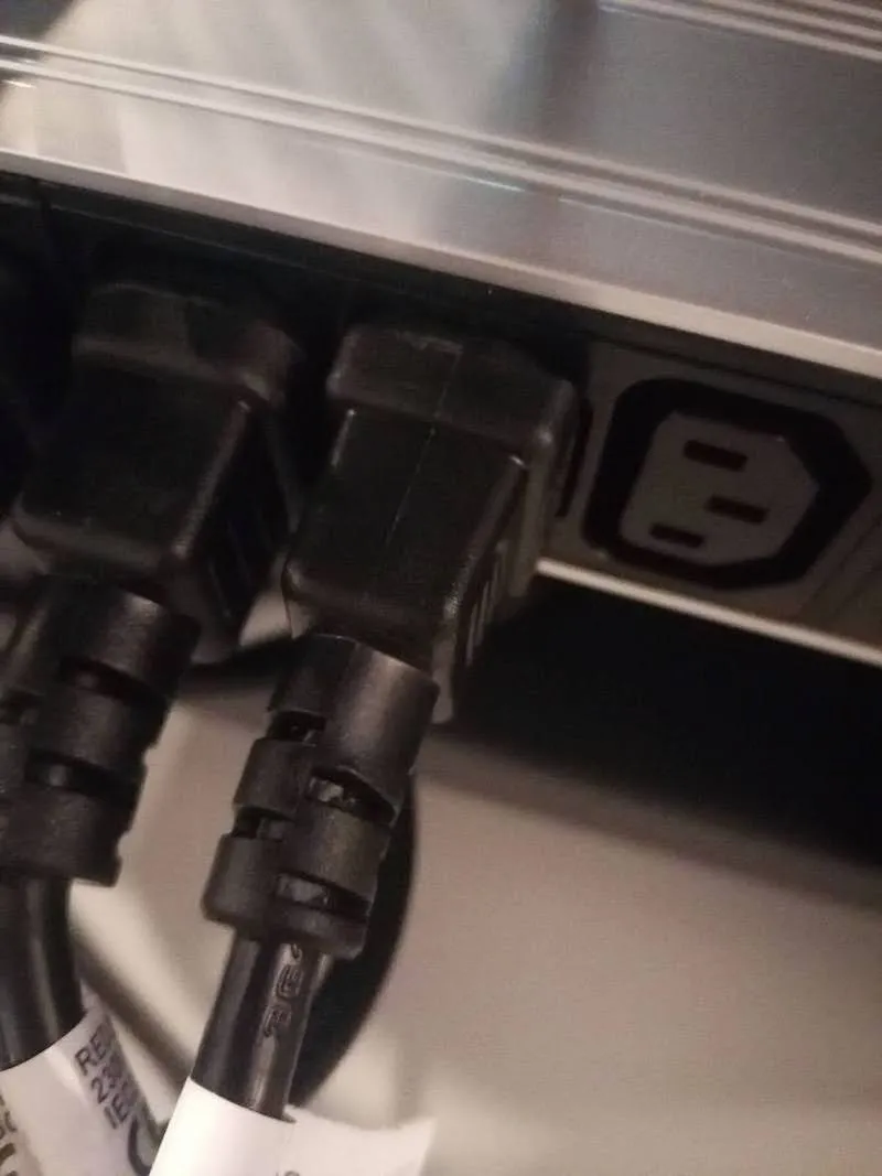
3.2.12. دوشاخه چند سوکت برق را به پریز دیواری وصل کنید.
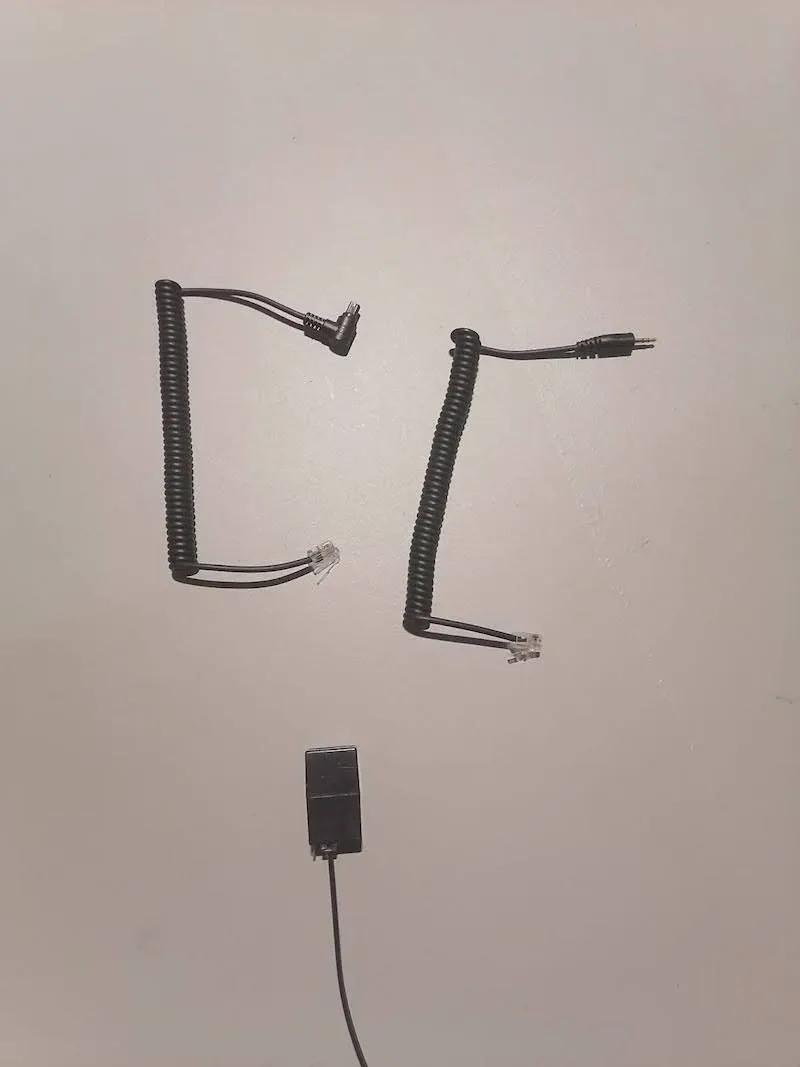
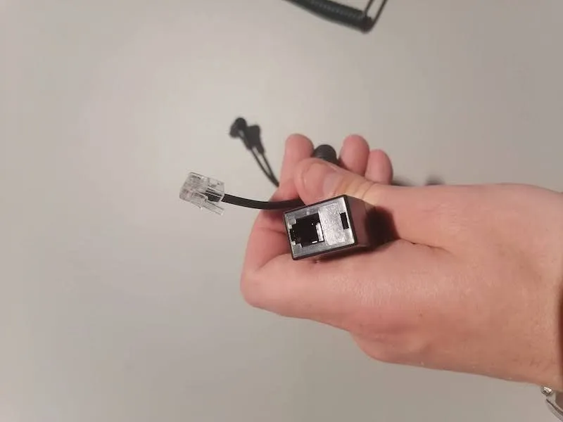
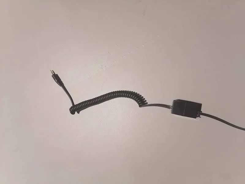
3.2.13. نوع ترمیناتور کابل شاتر را که به مدل دوربین شما منتقل می شود پیدا کنید و آن را به کوپلر کابل شاتر وصل کنید.
3.3. مونتاژ پس زمینه کاغذ
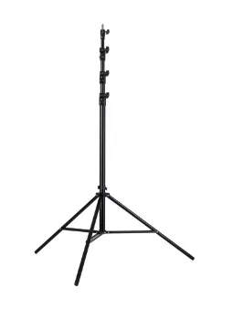
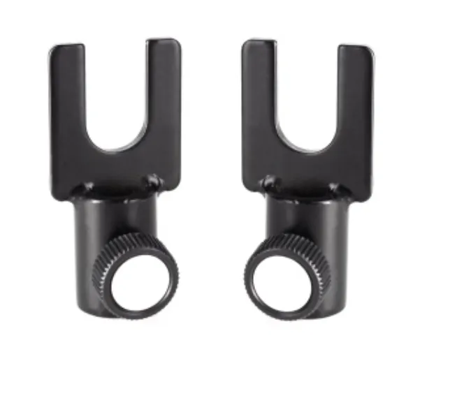
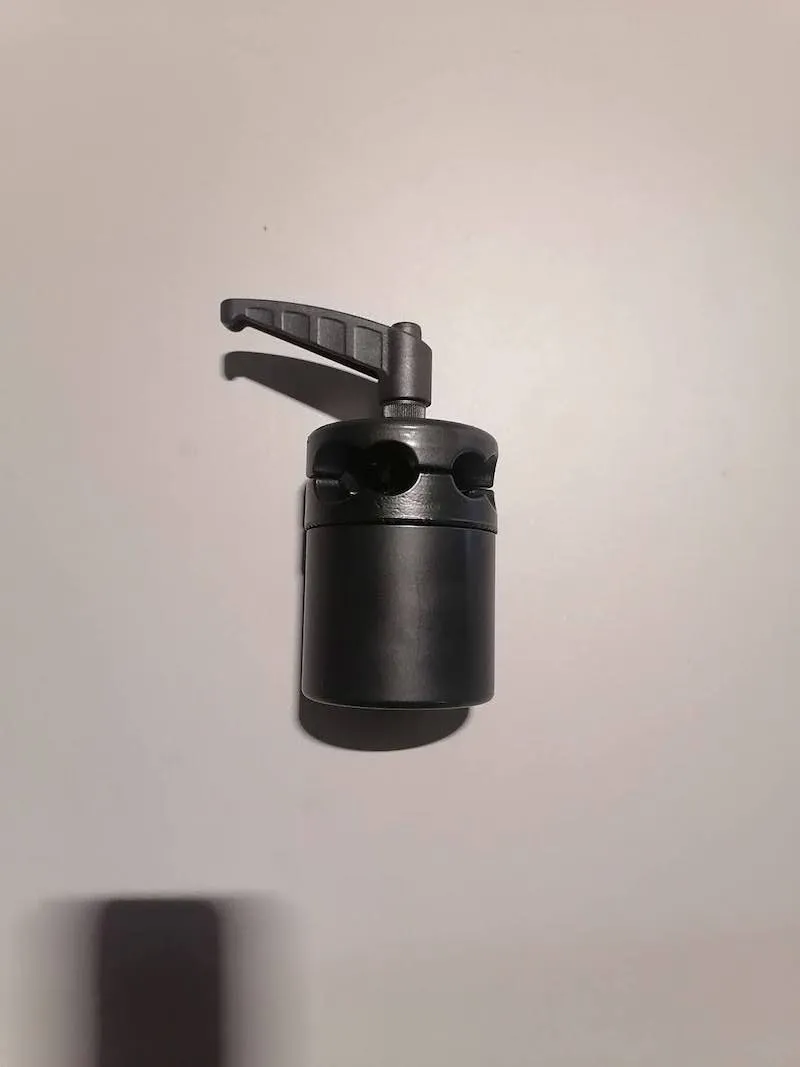
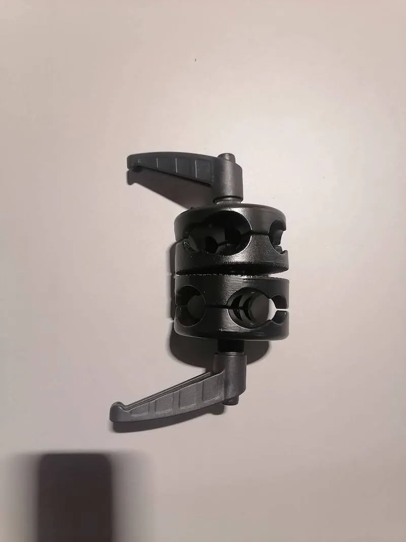
3.3.1. برای مونتاژ پس زمینه کاغذ، ابتدا دو پایه نور Master LS 13-B پیدا کنید. سپس، چنگال های ثابت W-2 را برای Expander Stud Set در بالای هر پایه نصب کنید.
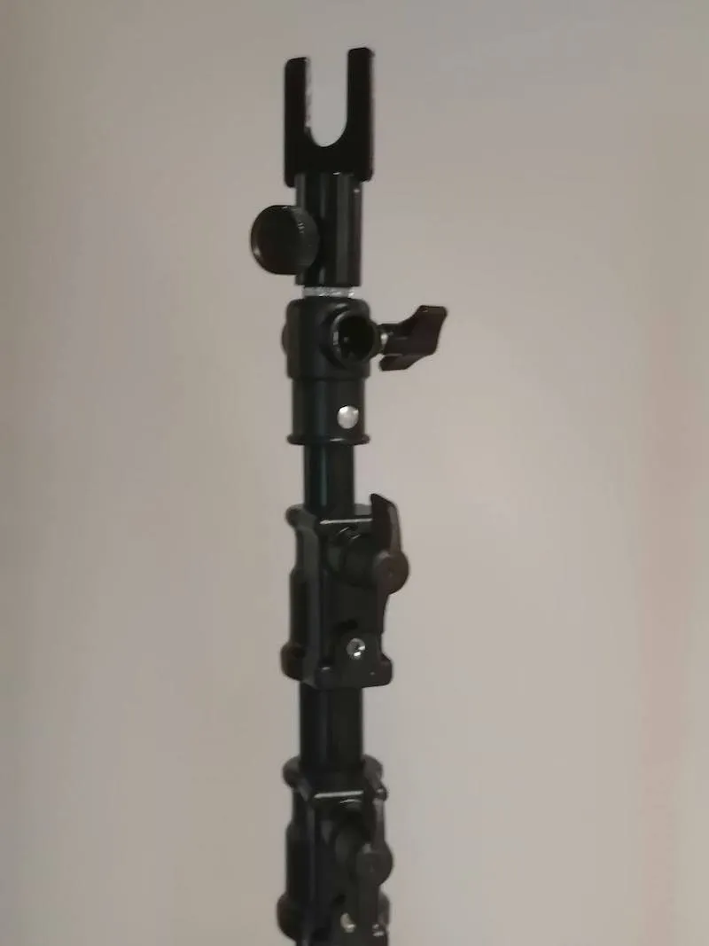
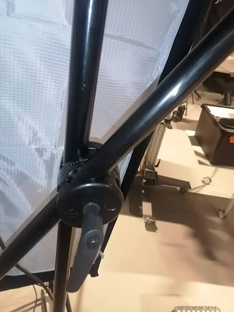
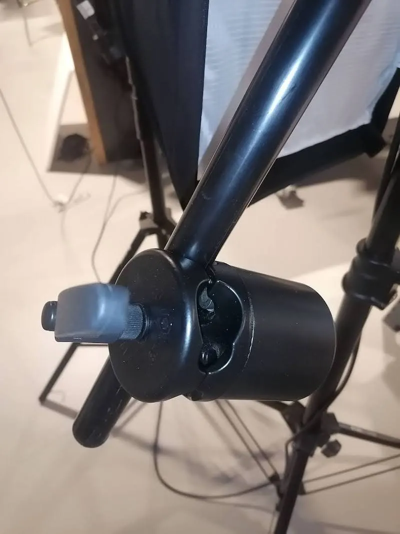
3.3.2. پس زمینه کاغذ را با گل میخ روی چنگال های ثابت دو سه پایه قرار دهید. یکی سمت چپ پس زمینه را نگه می دارد و دیگری سمت راست پس زمینه را نگه می دارد.
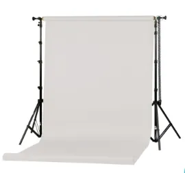
3.3.3. در مرحله بعد، ضبط صفحه نصب مجموعه گل میخ را تماشا کنید و مراحل ویدیو را تکرار کنید.
3.4 مونتاژ ربات مکعب V5 / V6
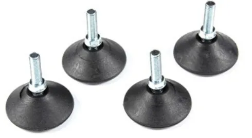
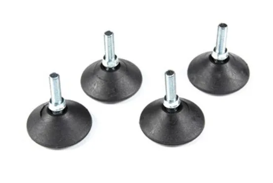
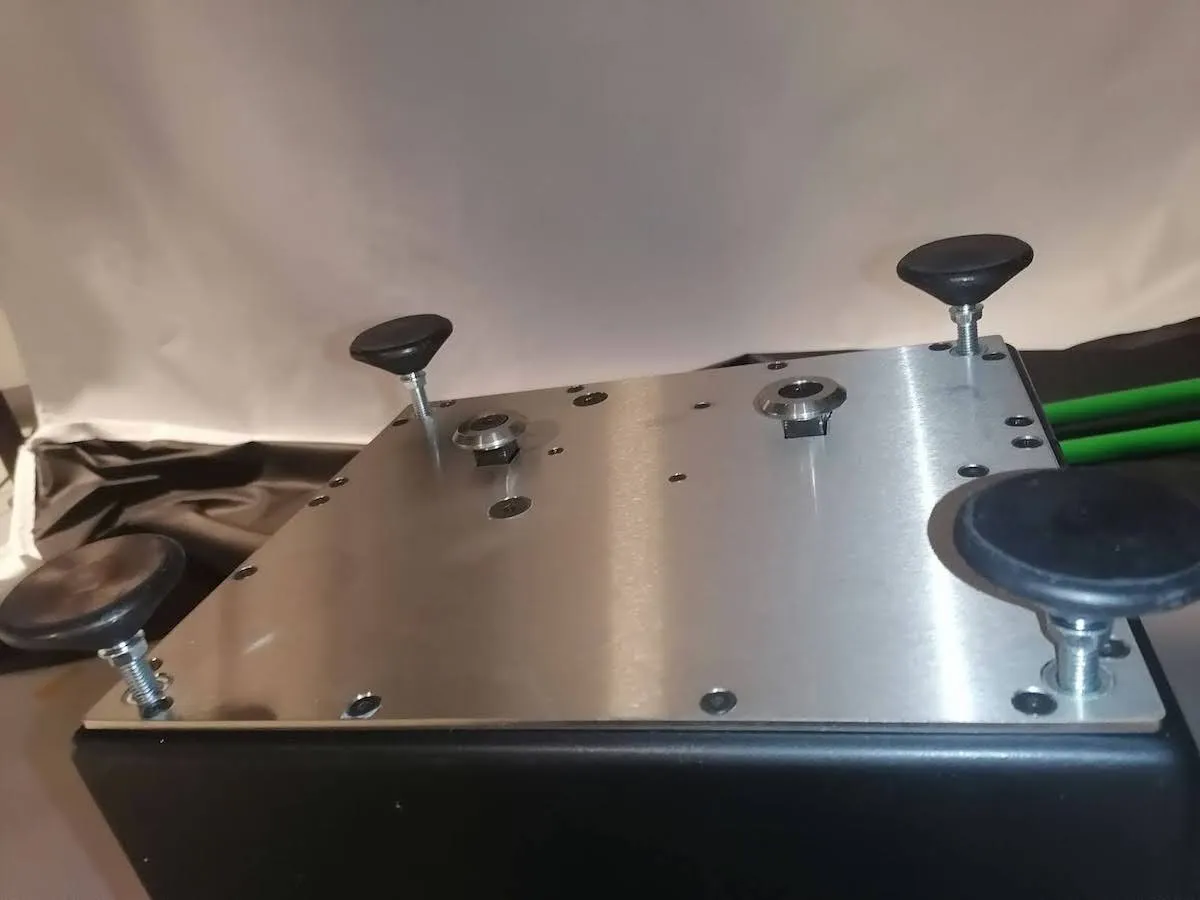
3.4.1. برای پیکربندی ربات مکعب برای پشتیبانی از نگهدارنده تنه مانکن چرخان، با باز کردن بسته بندی ربات و اتصال چهار پایه آن به پایین دستگاه شروع کنید.
3.4.2. در مرحله بعد، انتهای دیگر کابل موتور را به مکعب وصل کنید و هر دو پیچ را روی کانکتور ببندید.
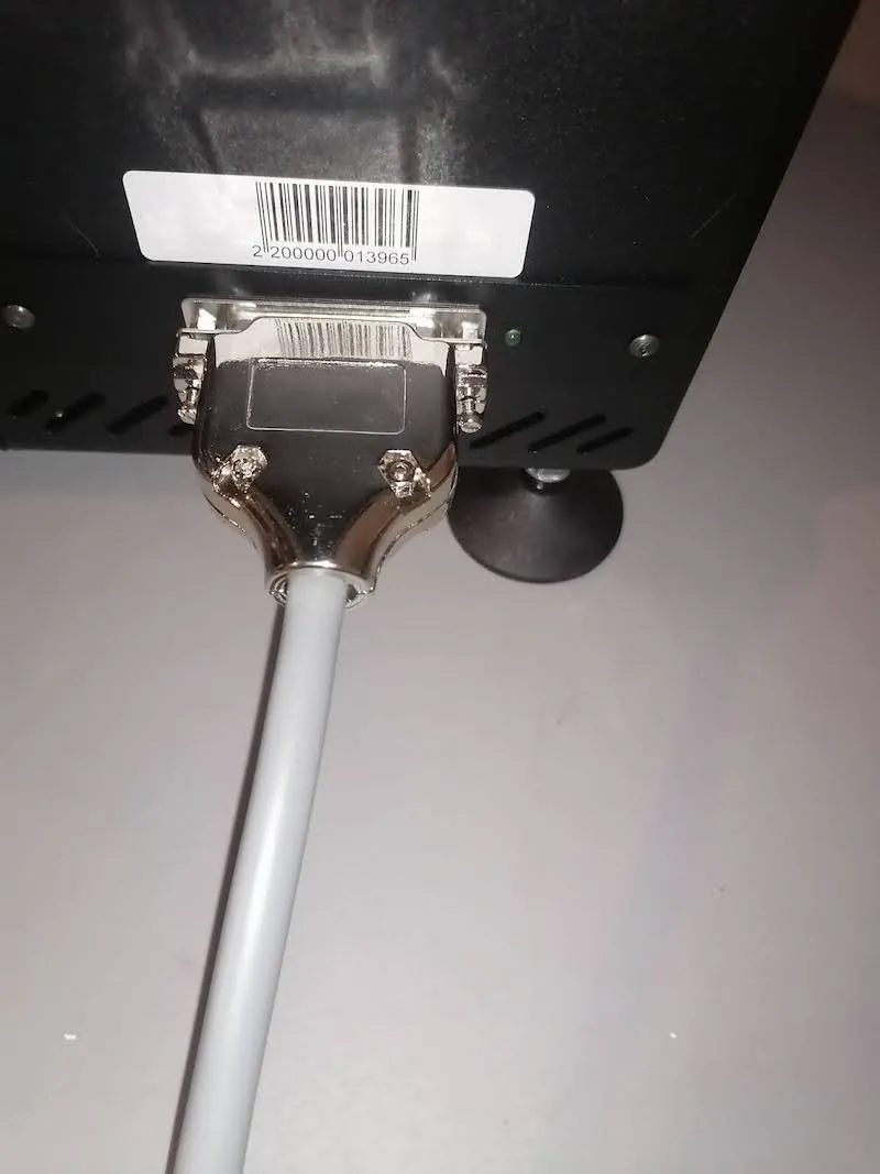
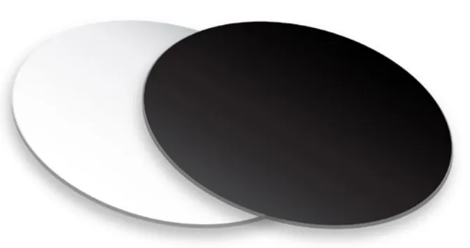
3.4.3. پس از اتصال دستگاه، ربات مکعب را روی زمین در مرکز پس زمینه سفید قرار دهید. مکعب را 1 متر از کاغذ فاصله بگیرید.
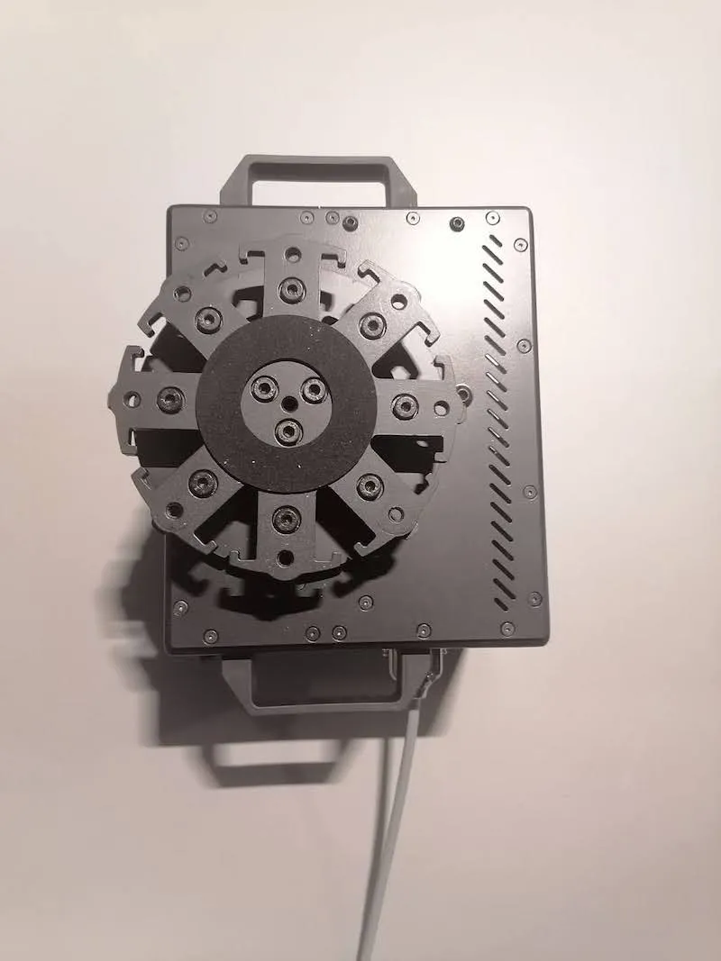
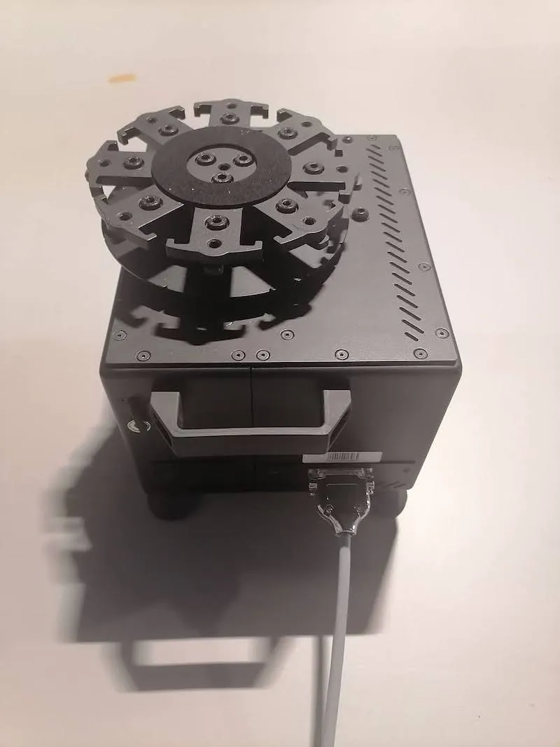
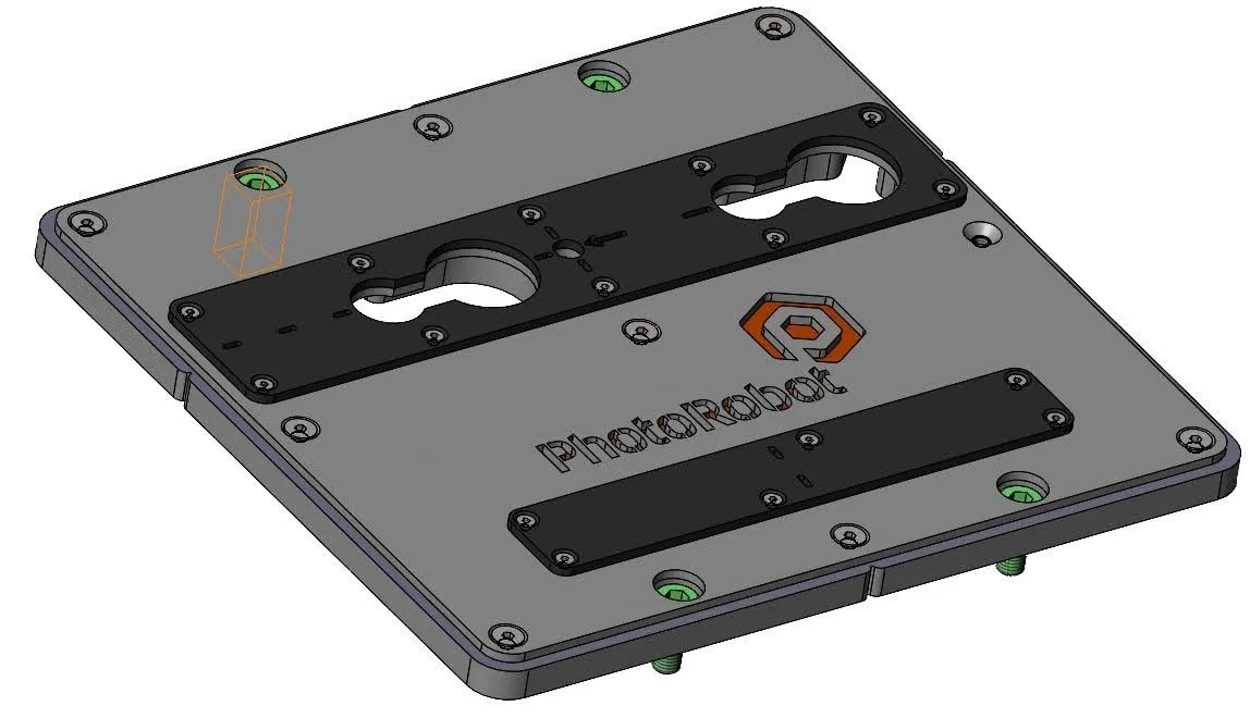
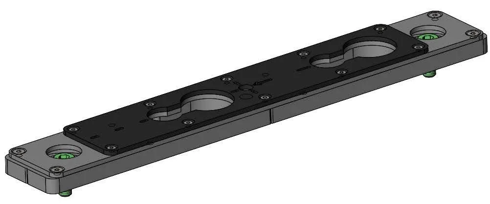
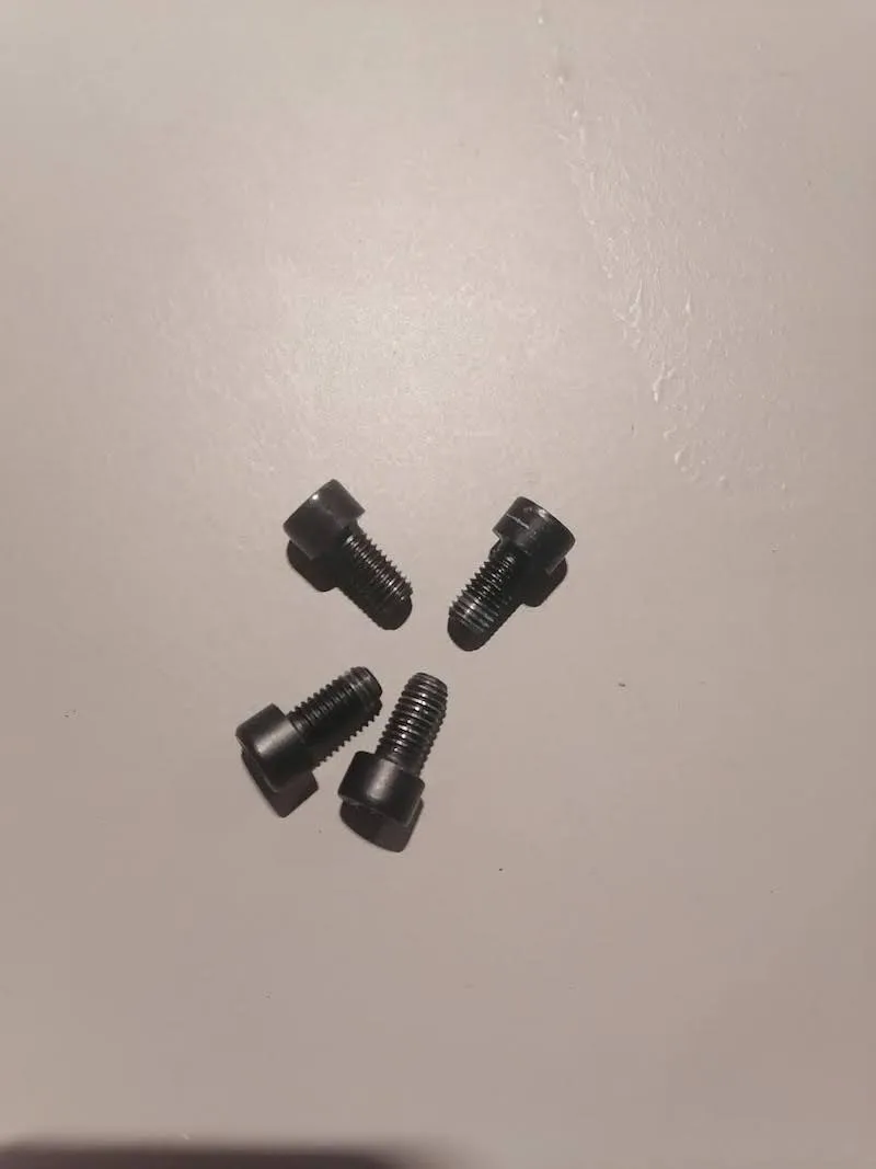
3.4.4. صفحه کاهش نگهدارنده تنه را روی بالای ربات مکعب قرار دهید و آن را با چهار پیچ ارائه شده در جای خود محکم کنید.
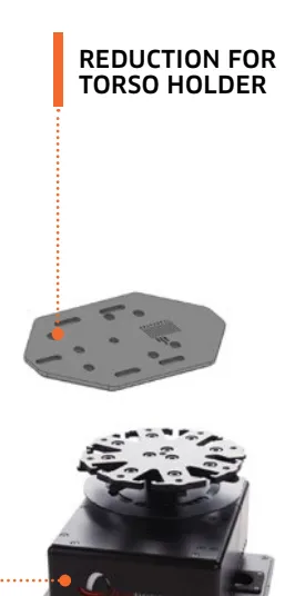
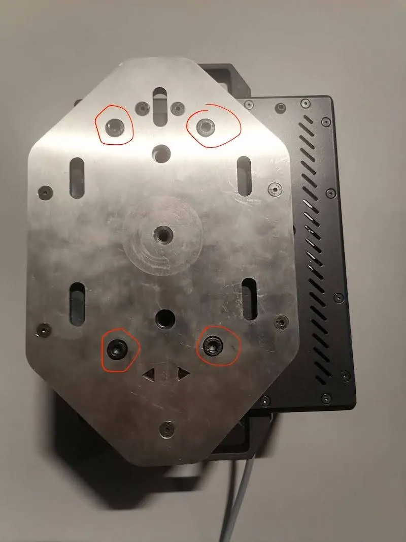
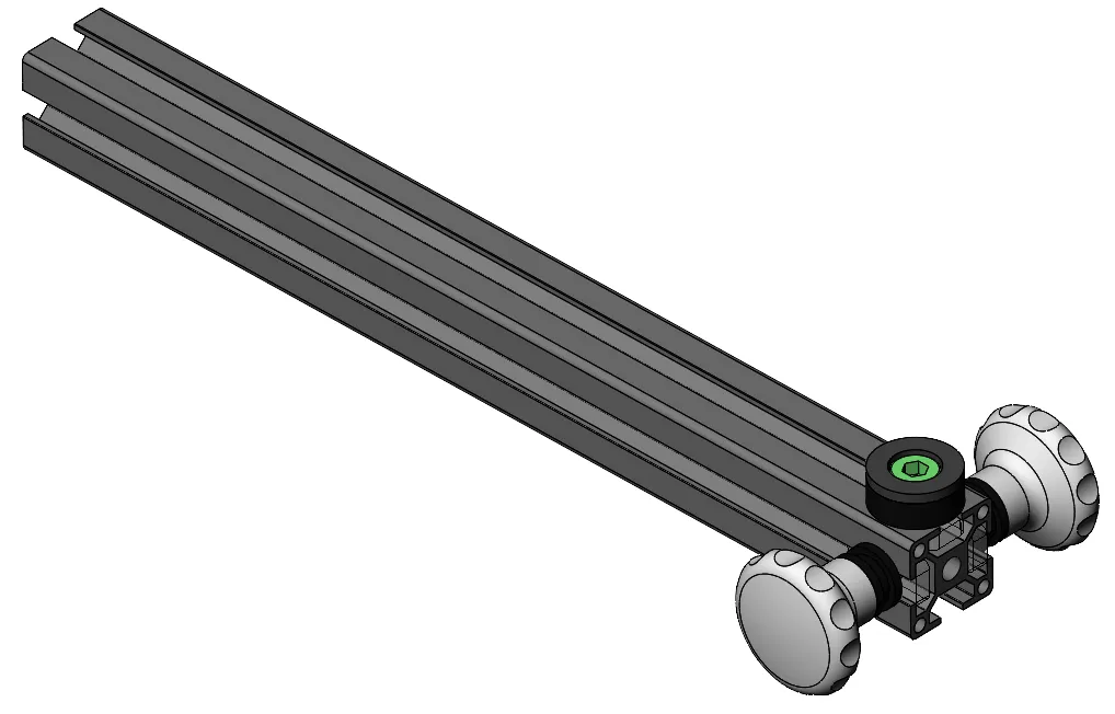
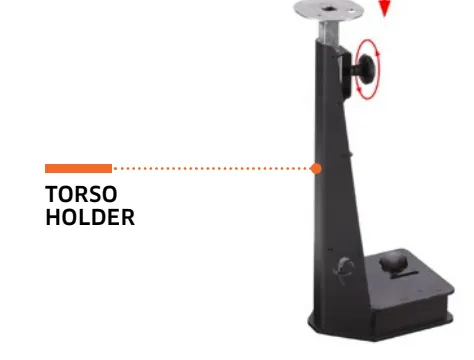
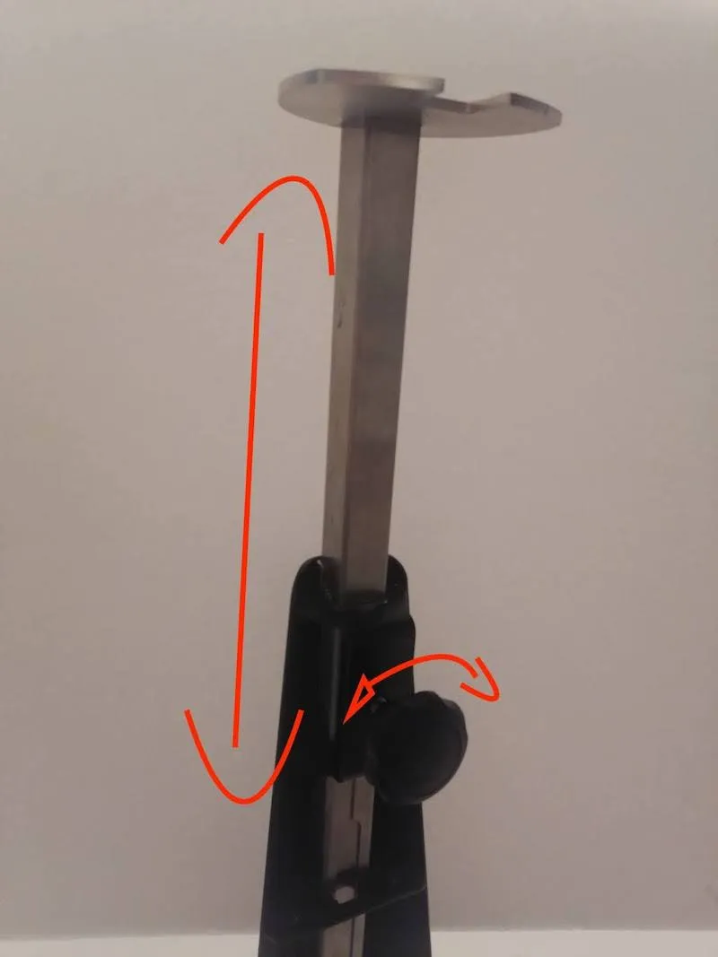
3.4.5. بدنه نگهدارنده تنه را روی صفحه کاهش قرار دهید و نگهدارنده تنه را با استفاده از پیچ دستی بزرگ در جای خود محکم کنید.
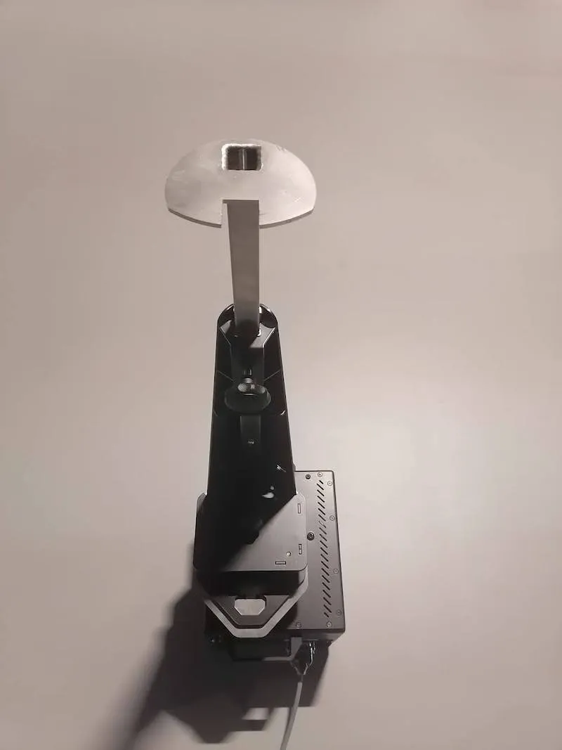
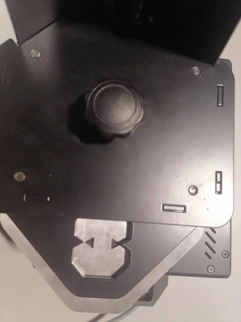
مهم: توجه دقیق به این مرحله ضروری است. اطمینان حاصل کنید که نمادهای مثلث از صفحه کاهش از طریق نگهدارنده تنه قابل مشاهده هستند. این بدان معنی است که نگهدارنده تنه به درستی نصب شده است.
3.4.6. در این مرحله، توجه داشته باشید که ارتفاع تنه با شل کردن و سفت کردن پیچ دستی و کشیدن اکستنشن بالاتر یا پایین قابل تنظیم است.
3.5. راه اندازی چراغ های فلاش
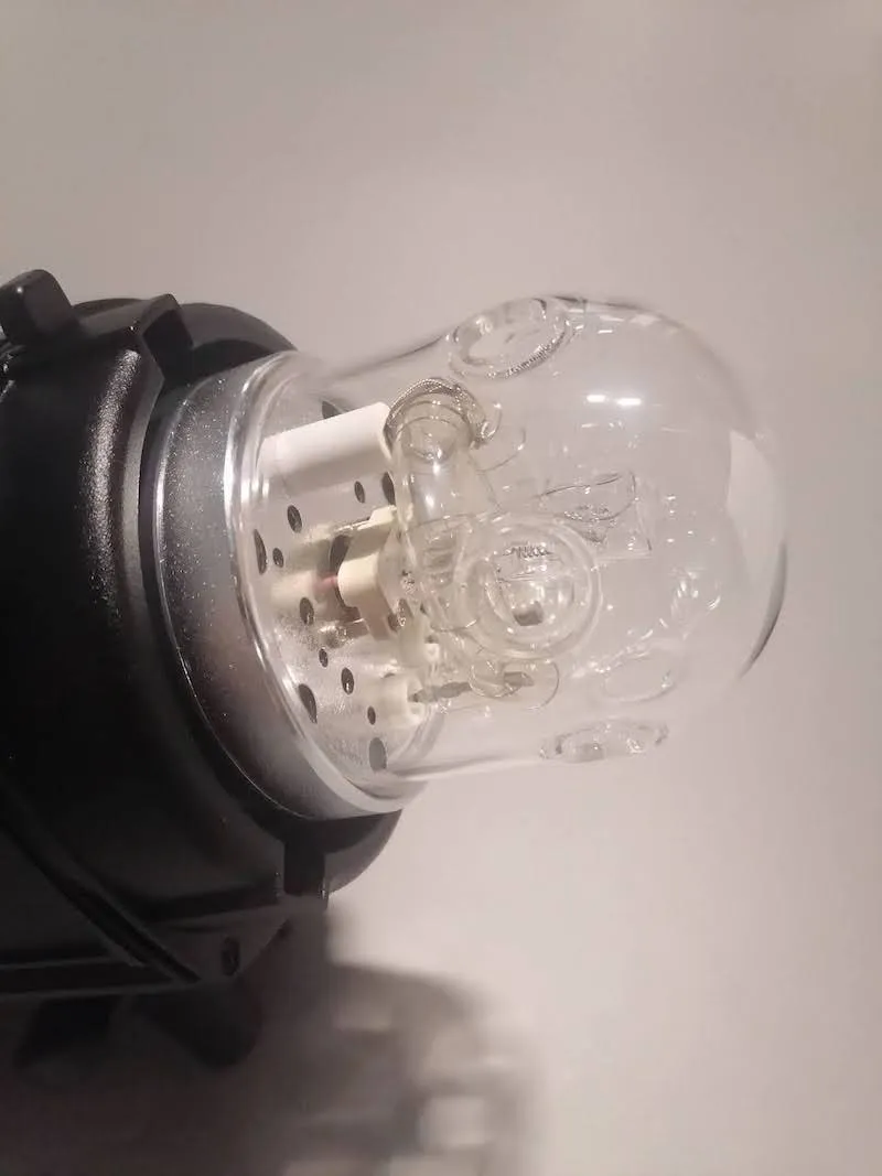
3.5.1. برای راه اندازی چراغ های فلاش با ربات مکعب، ابتدا چراغ های فلاش را از جعبه باز کنید و سپس لامپ خلبان را در هر چراغ قوه قرار دهید.
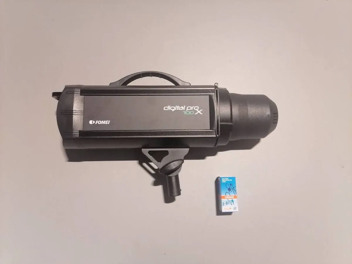
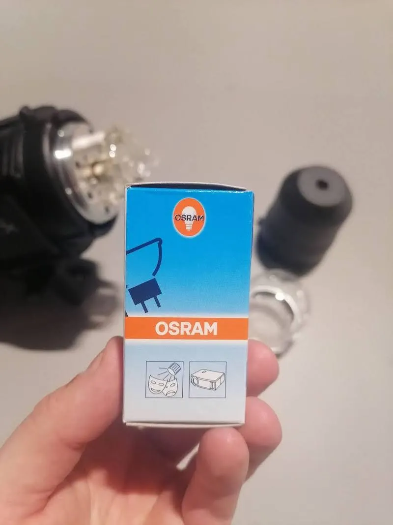
توجه داشته باشید: برای قرار دادن لامپ خلبان ، شیشه را با دقت از صفحه اصلی باز کنید. سپس، قبل از بیرون آوردن لامپ خلبان از جعبه کارتن، همین کار را برای محافظ شیشه ای لامپ اصلی انجام دهید. هنگام دست زدن به لامپ خلبان حتما از دستمال یا پارچه استفاده کنید، در غیر این صورت ممکن است طول عمر آن به شدت کاهش یابد. در مرحله بعد، لامپ خلبان را دقیقا مانند عکس های زیر در محل اتصال قرار دهید.
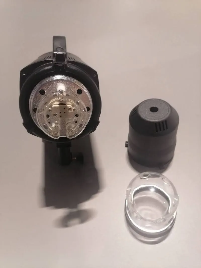
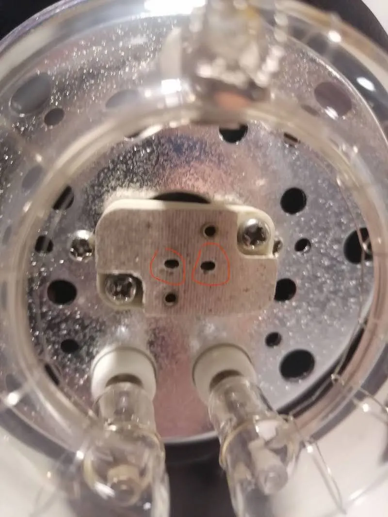
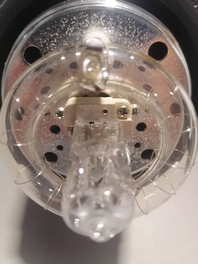
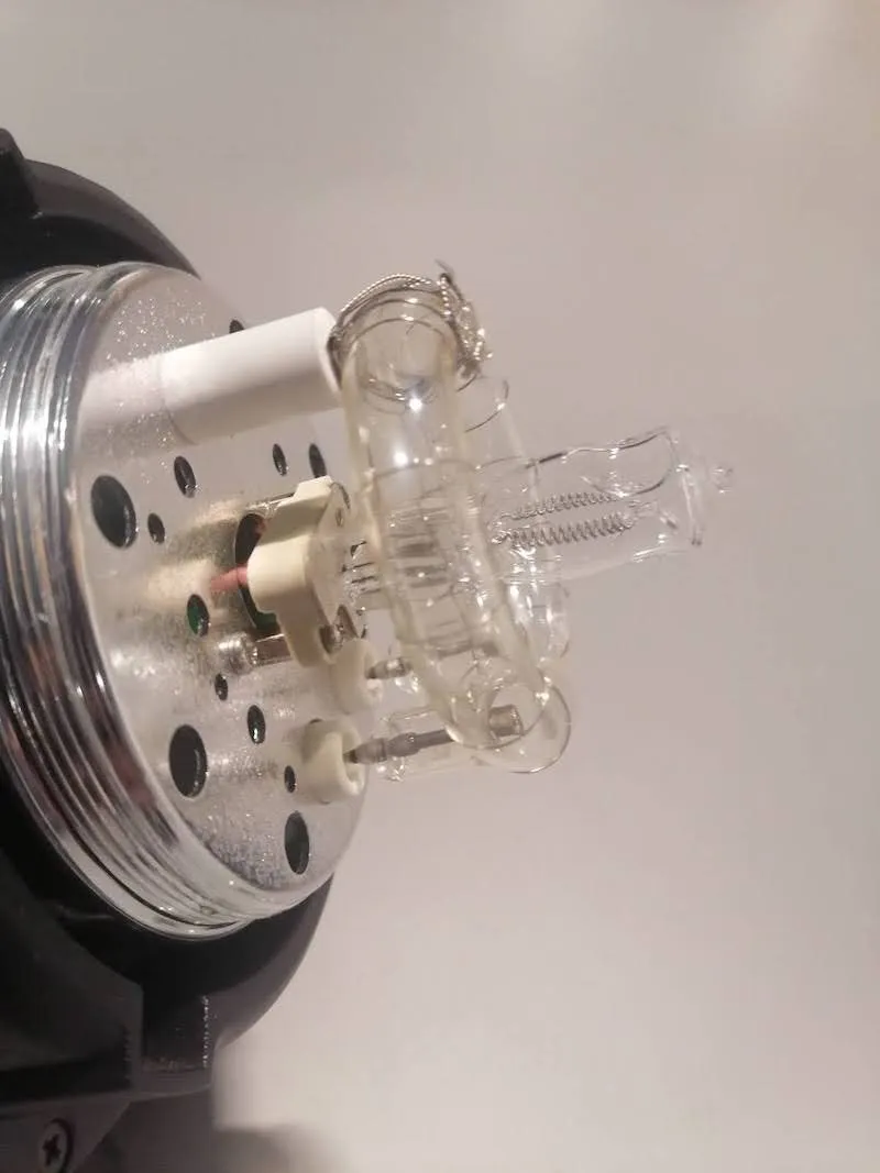
وقتی آماده شدید، به یاد داشته باشید که محافظ شیشه را دوباره روشن کنید و سپس مراحل قبلی را برای مونتاژ هر چراغ تکرار کنید.
3.5.2. پس از راه اندازی لامپ های پیلوت و تعویض محافظ شیشه ای آنها، کابل های برق را به تمام چراغ های قوه وصل کنید.
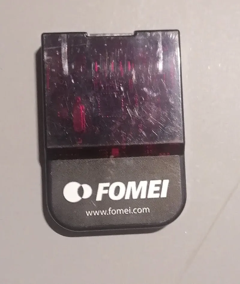
3.5.3. سپس، گیرنده ها را در هر چراغ قرار دهید و برچسب های FOMEI را برای جهت گیری در نظر بگیرید.
3.5.4. انتهای آزاد کابل های برق را از چراغ ها به چند سوکت برق وصل کنید.
3.5.5. روشن کردن همه چراغ های فلاش.
3.5.6. چراغ ها را به صورت فیزیکی در اطراف ربات در تنظیمات چراغ های توصیه شده زیر قرار دهید.
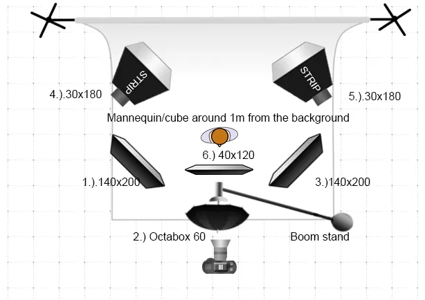
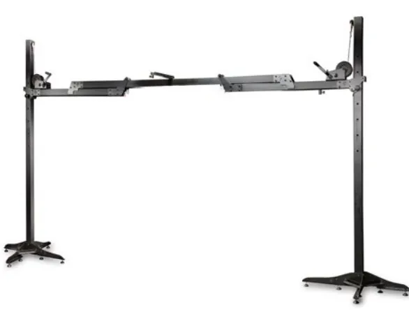
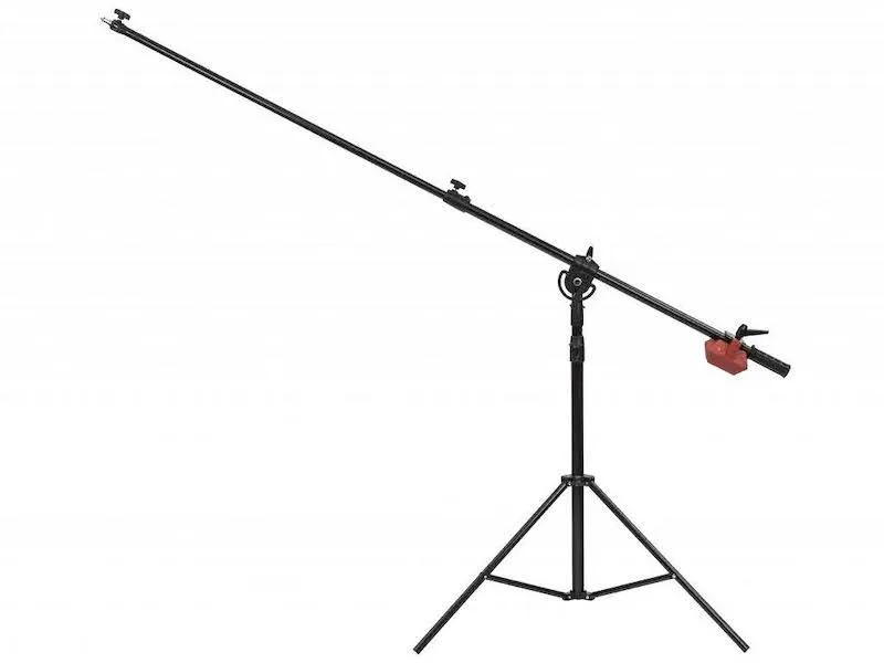
3.5.7. توجه داشته باشید که اگر یک پایه بوم مانند تنظیمات چراغ های توصیه شده نصب شده باشد، لازم است ابتدا پایه بوم بسازید. برای ساخت پایه بوم، به سه پایه، یک قطب بوم دیواری 1.5 متری و یک مجموعه بوم دیواری نیاز دارید.
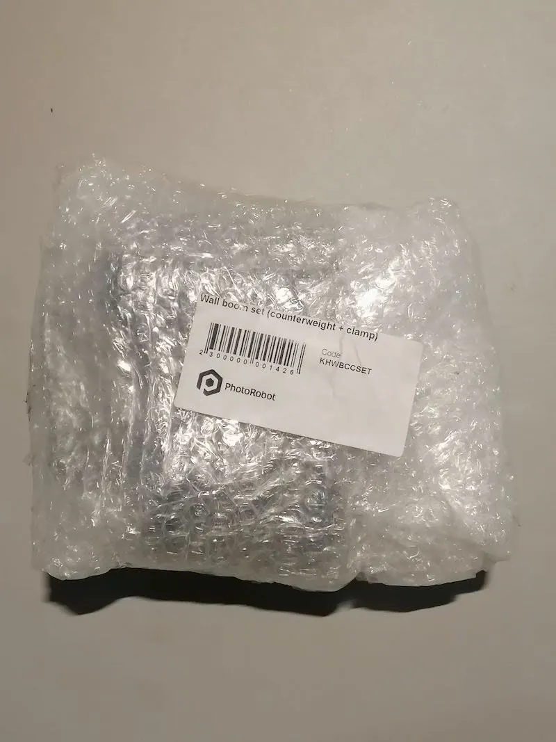
علاوه بر این، برای ساخت پایه بوم به تصاویر زیر مراجعه کنید.
الف) گیره قطب بوم دیواری:
ب) متعادل کردن وزن در انتهای قطب برای حمایت از نور:
ج) تصویر گویا از یک پایه بوم ساخته شده:
4. نرم افزار PhotoRobot _Controls
نرم افزار PhotoRobot _Controls برنامه کنترل کل ایستگاه کاری رباتیک Cube V5 / V6 / Compact را فراهم می کند. این شامل کنترل از راه دور بر روی تمام ربات ها، دوربین ها و نورپردازی است. این نرم افزار گردش کار را مدیریت می کند و عملکرد لازم را برای اتوماسیون موثر در زمینه پس پردازش فراهم می کند.
نرم افزار برنامه PhotoRobot _Controls برای دانلود از طریق حساب PhotoRobot شما در دسترس است. با تحویل دستگاه گنجانده نشده است. PhotoRobot _Controls نرم افزار App جداگانه از دستگاه خریداری می شود.
علاوه بر این، پس از راه اندازی برنامه نرم افزاری، توجه داشته باشید که رابط ممکن است به طور خودکار در "حالت جادوگر" شروع به کار کند. حالت جادوگر یک رابط کاربری ساده است. به عنوان مثال، اسکن بارکدها را برای شناسایی اشیا و شروع توالی های ضبط و پس پردازش به طور خودکار فراهم می کند.
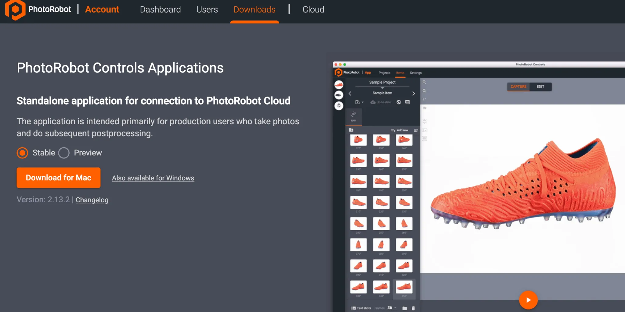
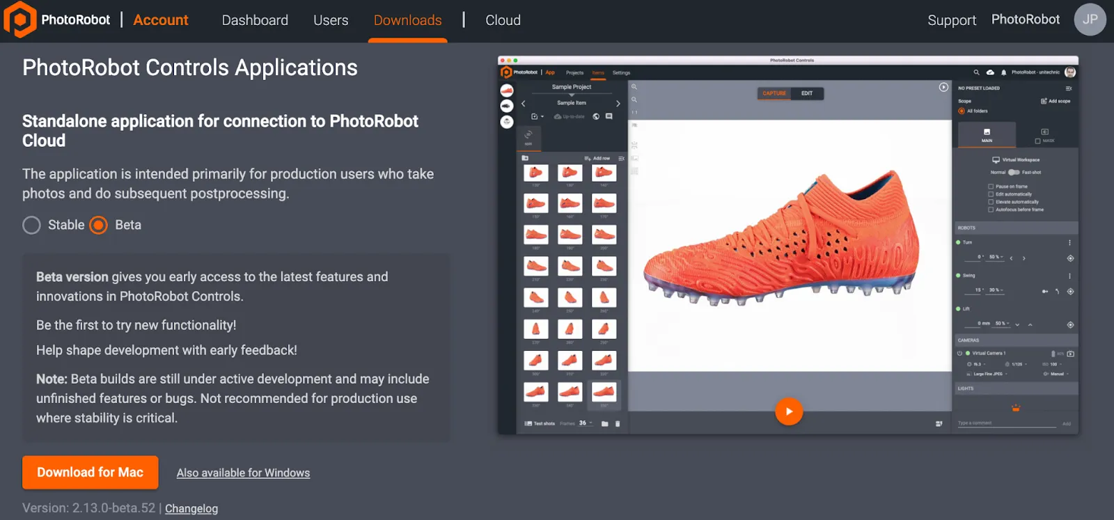
توجه داشته باشید: هر دو نسخه پایدار و نسخه پیش نمایش CAPP برای دانلود از طریق جادوگر نصب کننده در دسترس هستند. نسخه پایدار شامل جدیدترین نسخه CAPP است و نسخه های مکرر را دریافت می کند. در همین حال، نسخه پیش نمایش CAPP دسترسی زودهنگام به جدیدترین ویژگی ها و اصلاحاتی را فراهم می کند که در عرض چند روز پس از توسعه به نسخه پایدار منتقل می شوند. این به کاربران اجازه می دهد تا قبل از تماس با پشتیبانی، هر مشکلی را که در نسخه پیش نمایش رخ می دهد آزمایش کنند، زیرا اکثر مشکلات گزارش شده در نسخه پایدار قبلا در نسخه پیش نمایش حل شده است. با این حال، توجه داشته باشید که نسخه پیش نمایش برای استفاده تولیدی که در آن پایداری یک عامل حیاتی است، توصیه نمی شود. نسخه پیش نمایش در حال توسعه فعال است که ممکن است همچنان شامل ویژگی های ناقص یا اشکالات حل نشده باشد.
مهم: نسخه های قدیمی CAPP به دلیل خطر خرابی پایگاه داده برای توزیع مشتری یا عمومی در نظر گرفته نشده اند. نسخه های قدیمی CAPP فقط برای تکنسین های مجاز PhotoRobot برای توسعه داخلی یا برای موارد استفاده بسیار خاص قابل دسترسی هستند. برای یافتن آخرین نسخه پایدار و نسخه پیش نمایش CAPP، به آخرین نسخه های دانلود CAPP مراجعه کنید.
برای پشتیبانی یا عیب یابی PhotoRobot _Controls برنامه، به PhotoRobot شروع به کار مراجعه کنید.
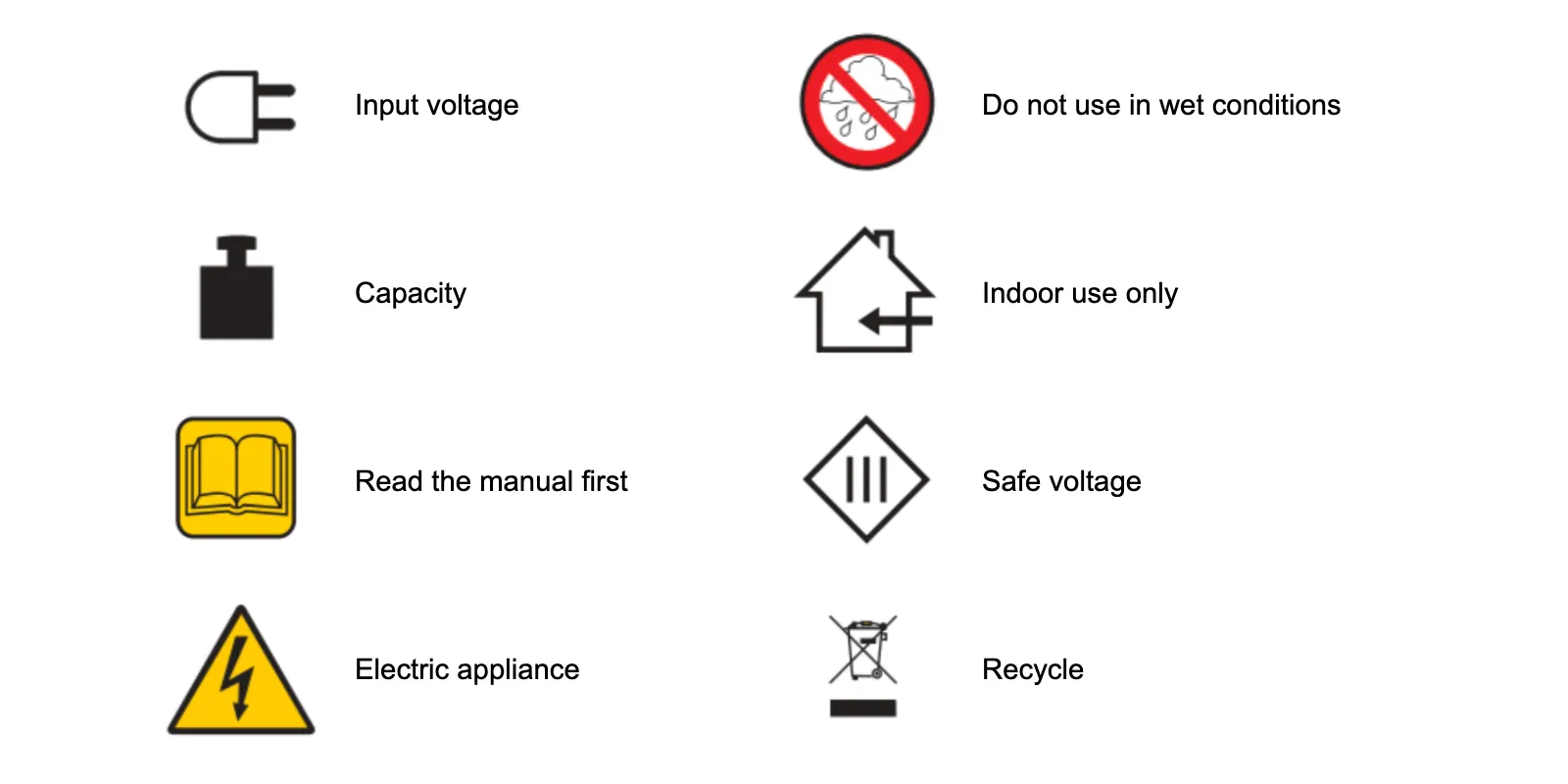
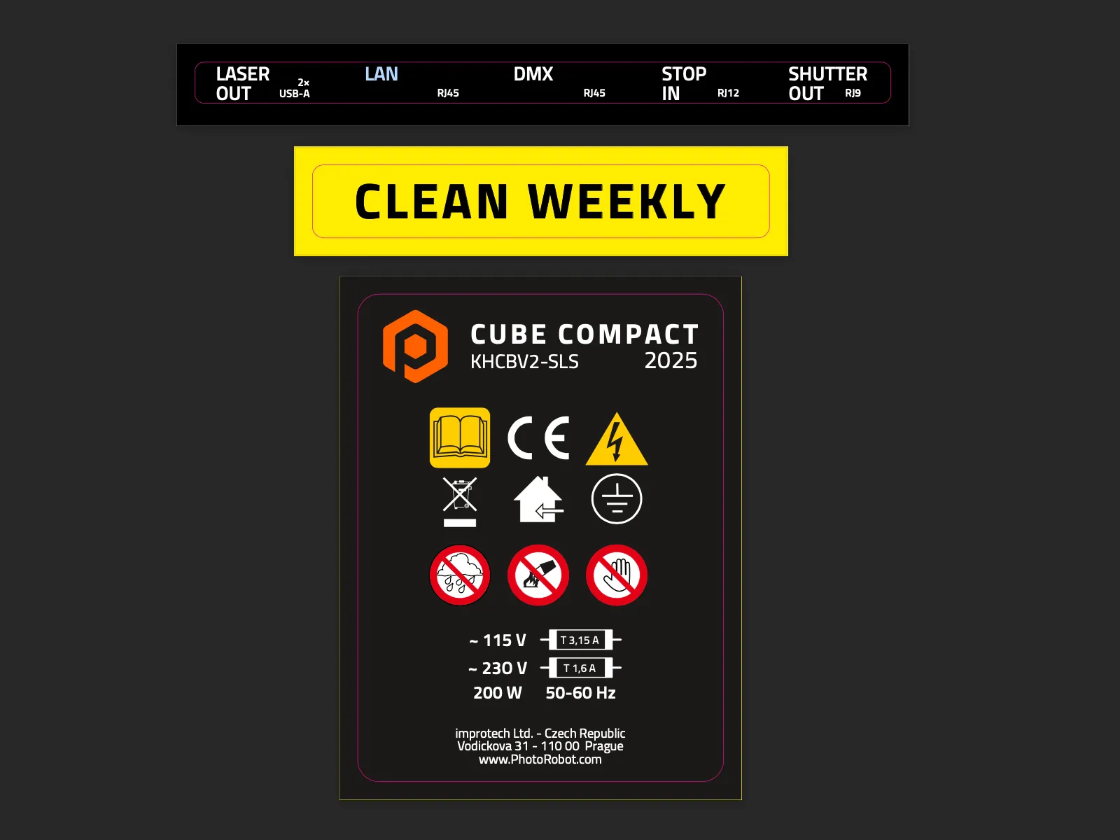
5. برچسب های اطلاعات
5.1. بررسی اجمالی نمادها
5.2 برچسب های جمع و جور مکعب


سری EOS Rebel


سری EOS DSLR


سری بدون آینه EOS M


سری PowerShot


نمای نزدیک / دستی

سری Canon EOS Rebel دوربین های DSLR مناسب برای مبتدیان را با کیفیت تصویر خوب، کنترل های بصری و ویژگی های همه کاره ارائه می دهد. این دوربین ها که برای علاقه مندان به عکاسی ایده آل هستند، فوکوس خودکار قابل اعتماد، صفحه نمایش لمسی با زاویه متغیر و ضبط ویدیوی Full HD یا 4K را ارائه می دهند.
اتصال
وضوح (MP)
وضوح
سری Canon EOS DSLR تصاویری با کیفیت بالا، فوکوس خودکار سریع و تطبیق پذیری ارائه می دهد که آن را هم برای عکاسی و هم برای تولید ویدیو ایده آل می کند.
اتصال
وضوح (MP)
وضوح
سری بدون آینه Canon EOS M طراحی جمع و جور را با عملکردی شبیه به DSLR ترکیب می کند. این دوربین ها با داشتن لنزهای قابل تعویض، فوکوس خودکار سریع و سنسورهای تصویر با کیفیت بالا، برای مسافران و سازندگان محتوایی که به دنبال قابلیت حمل بدون به خطر انداختن کیفیت تصویر هستند، عالی هستند.
اتصال
وضوح (MP)
وضوح
سری Canon PowerShot دوربین های جمع و جور و کاربرپسند را برای عکاسان و علاقه مندان معمولی ارائه می دهد. آنها با مدل های مختلف از دوربین های ساده نقطه ای گرفته تا دوربین های زوم پیشرفته، راحتی، کیفیت تصویر قوی و ویژگی هایی مانند تثبیت کننده تصویر و ویدیوی 4K را ارائه می دهند.
اتصال
وضوح (MP)
وضوح
دوربین های نزدیک و دستی Canon برای عکاسی و فیلمبرداری دقیق و نزدیک طراحی شده اند. جمع و جور و آسان برای استفاده، فوکوس دقیق، تصویربرداری با وضوح بالا و قابلیت های ماکرو همه کاره را ارائه می دهند که برای وبلاگ نویسی، عکاسی محصول و نمای نزدیک خلاقانه عالی است.


